Opel Frontera UBS. Service manual — part 1162
6E–14
ENGINE DRIVEABILITY AND EMISSIONS
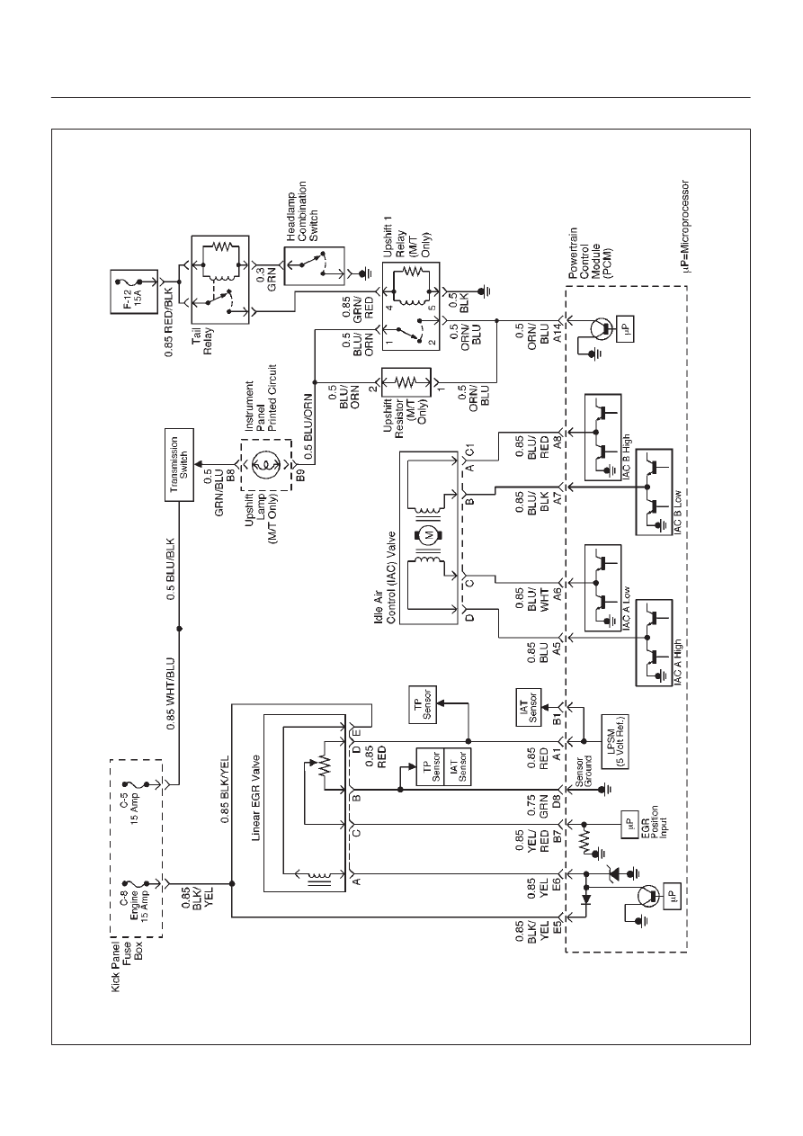
PCM Wiring Diagram (9 of 11) Except EXP and SOUTH AFRICA
D06RW099
6E–15
ENGINE DRIVEABILITY AND EMISSIONS
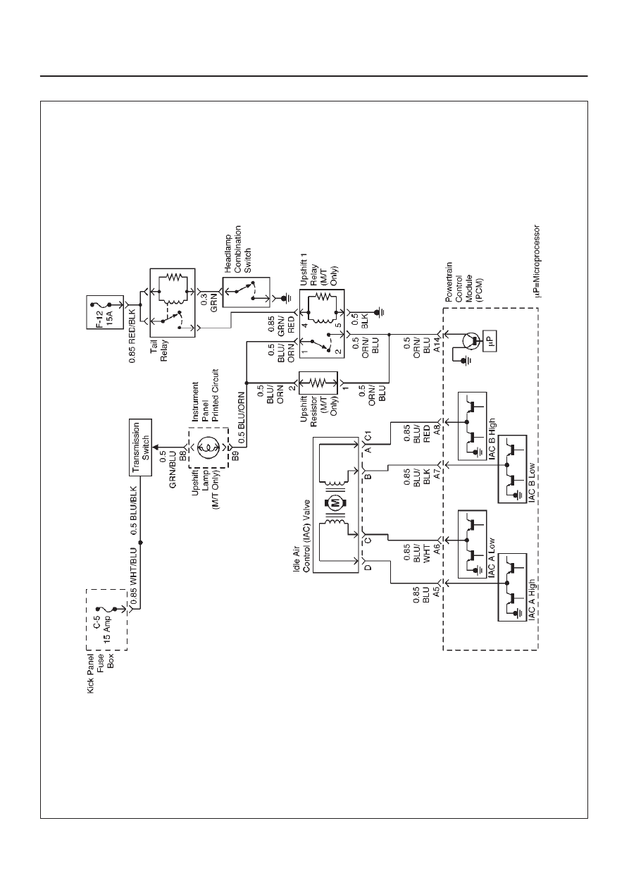
PCM Wiring Diagram (10 of 11) For EXPORT and SOUTH AFRICA
D06RW141
6E–16
ENGINE DRIVEABILITY AND EMISSIONS
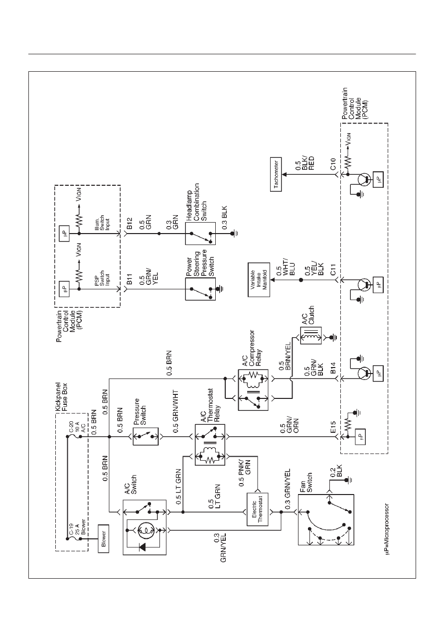
PCM Wiring Diagram (11 of 11)
D06RW136
6E–17
ENGINE DRIVEABILITY AND EMISSIONS
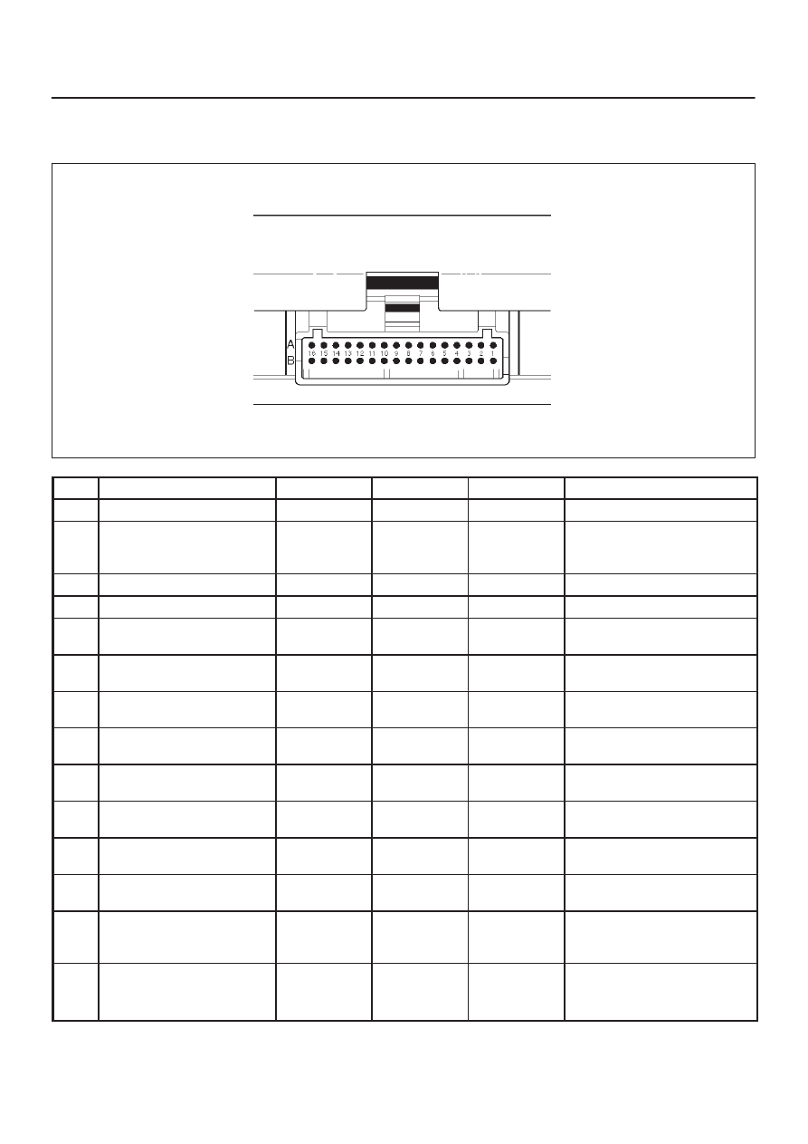
PCM Pinouts
PCM Pinout Table, 32-Way Red Connector – Row “A”
TS23344
PIN
PIN Function
Wire Color
IGN ON
ENG RUN
Refer To
A1
5 Volt Reference “A”
RED
5.0 V
5.0 V
Appropriate Sensor
A2
Knock Sensor
YEL
0.0 V DC
2mV AC
0.0 V DC
18mV AC
(at idle)
General Description and
Operation, Knock Sensor
A3
Not Used
—
—
—
—
A4
Battery Feed
WHT
B+
B+
Chassis Electrical
A5
Idle Air Control (IAC) “A”
High
BLU
B+/0.8 V
B+/0.8 V
General Description and
Operation, IAC
A6
IAC “A” Low
BLU/WHT
B+/0.8 V
B+/0.8 V
General Description and
Operation, IAC
A7
IAC “B” Low
BLU/BLK
B+/0.8 V
B+/0.8 V
General Description and
Operation, IAC
A8
IAC “B” High
BLU/RED
B+/0.8 V
B+/0.8 V
General Description and
Operation, IAC
A9
Automatic Transmission
Fluid (ATF) Lamp
ORN/BLU
B+
B+
Automatic Transmission
(4L30E)
A10
Winter Lamp
PNK/GRN
B+
B+
Automatic Transmission
(4L30E)
A11
Power Lamp
GRY/WHT
B+
B+
Automatic Transmission
(4L30E)
A12
Antilock Brake System
(ABS)
GRY
B+
B+
Antilock Brake System
A13
Malfunction Indicator
(Check Engine or MIL)
Lamp
BLU
0.0 V
B+
Chassis Electrical
A14
“Check Transmission”
Lamp Driver (AT)
ORN/BLK
B+
B+
Chassis Electrical
Up Shift Lamp Driver (MT)
ORN/BLU
Нет комментариевНе стесняйтесь поделиться с нами вашим ценным мнением.
Текст