Opel Frontera UBS. Service manual — part 2157

6E–201
ENGINE DRIVEABILITY AND EMISSIONS
DTC P0341 – CMP Sensor Circuit Performance
(Cont'd)
Step
No
Yes
Value(s)
Action
10
1. Check for poor connections at the PCM.
2. If a problem is found, repair it as necessary.
Was a problem found?
—
Verify repair
Go to
Step 11
11
Backprobe the PCM connector with a DVM to monitor
voltage on the camshaft position input signal circuit
while cranking the engine with the sensor connected.
(Use rubber band, tape, or an assistant to keep the
DVM lead in contact with the sensor terminal during this
test.)
Does the voltage toggle between the specified values?
4-0 V
Go to
Step 15
Go to
Step 12
12
1. Remove the CMP sensor from the engine front
cover (leave the sensor wiring connected).
2. Place a magnet on the CMP sensor.
(If you use a magnet that is too small to cover the face
of the sensor, test on every part of the sensor face
because only a small area will respond to this test.)
Does the DVM display a voltage near the specified
value?
0 V
Go to
Step 13
Go to
Step 14
13
Replace the faulty or missing camshaft position sensor
magnet.
Is the action complete?
—
Verify repair
—
14
Replace the camshaft position sensor.
Is the action complete?
—
Verify repair
—
15
Replace the PCM.
IMPORTANT: The replacement PCM must be
programmed. Refer to
UBS 98model year Immobilizer
Workshop Manual.
Is the action complete?
—
Verify repair
—
6E–202
ENGINE DRIVEABILITY AND EMISSIONS
Diagnostic Trouble Code (DTC) P0342 CMP Sensor Circuit Low
D06RW032
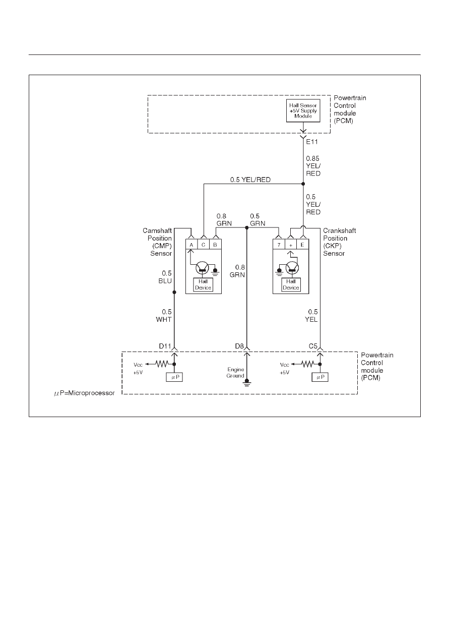
Circuit Description
The CMP signal produced by the camshaft position
(CMP) sensor pulses when the engine is running and
crankshaft position (CKP) sync pulses are also being
received. The hall type CMP sensor and the CKP sensor
share 5 V and ground connections at the powertrain
control module (PCM). The third wire at the sensor is a
signal circuit to the PCM. The PCM uses the CMP signal
pulses to initiate sequential fuel injection. The PCM
constantly monitors the number of pulses on the CMP
signal circuit and compares the number of CMP pulses to
the number of 58X reference pulses received. If the PCM
does not receive pulses on the CMP reference circuit,
DTC P0342 will set and the PCM will initiate injector
sequence without the CMP signal with a one in six chance
that injector sequence is correct. The engine will continue
to start and run normally, although the misfire diagnostic
will be affected if a misfiring condition occurs.
Conditions for Setting the DTC
D
The engine is running.
D
The CMP sensor signal is not received by the PCM
once every 6 cylinders.
D
The above condition occurs for 10 seconds.
Action Taken When the DTC Sets
D
The PCM will illuminate the malfunction indicator lamp
(MIL) after the second consecutive trip in which the
fault is detected.
D
The PCM will initiate injector sequence without the
CMP signal with a one in six chance that the injector
sequence is correct.
D
The PCM will store conditions which were present
when the DTC was set as Freeze Frame and in the
Failure Records data.

6E–203
ENGINE DRIVEABILITY AND EMISSIONS
Conditions for Clearing the MIL/DTC
D
DTC P0342 can be cleared by using Tech 2 “Clear Info”
function or by disconnecting the PCM battery feed.
Diagnostic Aids
An intermittent may be caused by a poor connection,
rubbed-through wire insulation or a wire broken inside the
insulation. Check for:
D
Poor connection – Inspect the PCM harness and
connectors for improper mating, broken locks,
improperly formed or damaged terminals, and poor
terminal to wire connection.
D
Damaged harness – Inspect the wiring harness for
damage. If the harness appears to be OK, disconnect
the PCM, turn the ignition on and observe a voltmeter
connected to the CMP signal circuit at the PCM
harness connector while moving connectors and
wiring harnesses related to the ICM and the CMP
sensor. A change in voltage will indicate the location
of the fault.
Test Description
Number(s) below refer to the step number(s) on the
Diagnostic Chart.
2. Ensures that the fault is present.
14.Determines whether the fault is being caused by a
missing camshaft magnet or a faulty PCM. The
voltage measured in this step should read around 4
volts, toggling to near 0 volts when the CMP sensor
interfaces with the camshaft magnet.
DTC P0342 – CMP Sensor Circuit Low
Step
Action
Value(s)
Yes
No
1
Was the “On-Board Diagnostic (OBD) System Check”
performed?
—
Go to
Step 2
Go to
OBD
System
Check
2
1. Ignition “ON.”
2. Review and record Tech 2 Failure Records data.
3. Operate the vehicle within Failure Records
conditions as noted.
4. Using Tech 2, monitor “Specific DTC” information
for DTC P0342 until the DTC P0342 test runs.
5. Note test result.
Does Tech 2 indicate DTC P0342 failed this ignition?
—
Go to
Step 3
Refer to
Diagnostic
Aids
3
1. Ignition “ON.”
2. Disconnect the CMP sensor.
3. Measure the voltage between the sensor feed
circuit and the sensor ground circuit at the CMP
sensor harness connector.
Does the voltage measure near the specified value?
4-6 V
Go to
Step 7
Go to
Step 4
4
1. Ignition “OFF,” disconnect the PCM and the CMP
sensor.
2. Check for poor connections at the camshaft
position sensor.
3. If a problem is found, repair it as necessary.
Was a problem found?
—
Verify repair
Go to
Step 5
5
1. Check for poor connections at the PCM.
2. If a problem is found, repair it as necessary.
Was a problem found?
—
Verify repair
Go to
Step 6
6
1. Check the following circuits between the PCM and
the CMP sensor:
D
The sensor feed circuit. Open or short to
ground?
D
The sensor ground circuit. Open or short to
voltage?
2. If a problem is found, repair as necessary.
Was a problem found?
—
Verify repair
—

6E–204
ENGINE DRIVEABILITY AND EMISSIONS
DTC P0342 – CMP Sensor Circuit Low
(Cont'd)
Step
No
Yes
Value(s)
Action
7
1. Ignition “ON,” engine “OFF.”
2. Measure the voltage between the CMP sensor
signal circuit and the sensor ground circuit at the
CMP sensor harness connector.
Does the voltage measure near the specified value?
4-6 V
Go to
Step 8
Go to
Step 9
8
1. Turn the ignition “OFF.”
2. Disconnect the PCM and connect a DVM to monitor
voltage on the camshaft position signal circuit at the
PCM connector.
3. Ignition “ON.”
4. Monitor the voltage display on the DVM while
repeatedly touching the CMP sensor signal circuit
at the CMP sensor connector with a test light to
ground.
Does the DVM voltage display switch between 0 and
approximately 5 volts when the test light is touched to
the CMP sensor signal circuit?
—
Go to
Step 12
Go to
Step 9
9
1. Ignition “OFF.”
2. Leave the PCM disconnected.
3. Ignition “ON.”
4. Probe the camshaft position signal circuit at the
PCM connector with a test light to B+.
5. If the test light is “ON,” locate and repair the short to
ground in the camshaft position input signal circuit.
Was either circuit shorted to ground?
—
Verify repair
Go to
Step 10
10
1. Ignition “OFF.”
2. Leave the PCM disconnected.
3. Ignition “ON.”
4. Probe the camshaft position signal circuit with a test
light to ground.
5. If the test light is “ON,” locate and repair the short to
voltage in the camshaft position input signal circuit.
Was the test light “ON”?
—
Verify repair
Go to
Step 11
11
1. Ignition “OFF,” disconnect the PCM (leave the CMP
sensor disconnected).
2. Ignition “ON,” check the following circuit:
D
The CMP sensor signal circuit for an open.
3. If a problem is found, repair it as necessary.
Was a problem found?
—
Verify repair
—
12
1. Ignition “ON.”
2. Remove the CMP sensor from the engine front
cover (leave the sensor wiring connected).
3. Place a magnet on the CMP sensor. If you use a
magnet that is too small to cover the face of the
sensor, test on every part of the sensor face
because only a small area will respond to this test.
Does the DVM display a voltage near the specified
value?
0 V
Go to
Step 14
Go to
Step 13
13
Replace the camshaft position sensor.
Is the action complete?
—
Verify repair
—
Нет комментариевНе стесняйтесь поделиться с нами вашим ценным мнением.
Текст