Opel Frontera UBS. Service manual — part 1948
DIFFERENTIAL (REAR 244mm) 4A2B–15
Disassembly
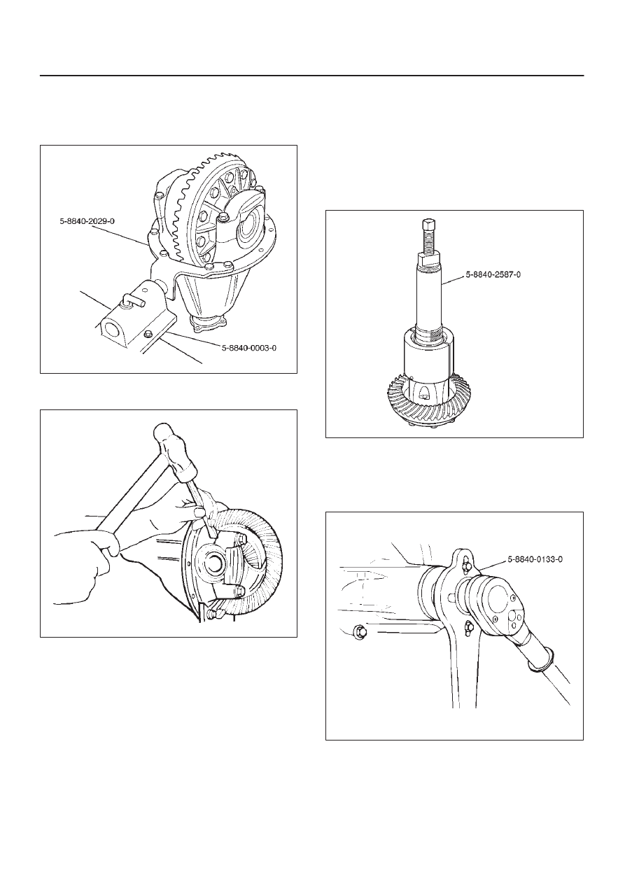
1. Using holding fixture 5–8840–2029–0 and holding
fixture base 5–8840–0003–0, fix the differential
assembly to the bench.
425RW058
2. Apply a setting mark to the side bearing cap and the
differential carrier then remove bearing cap.
425RS009
3. Remove differential cage assembly.
4. Remove side bearing outer race. After removal, keep
the right and left hand side bearing assemblies
separate to maintain inner and outer race
combinations.
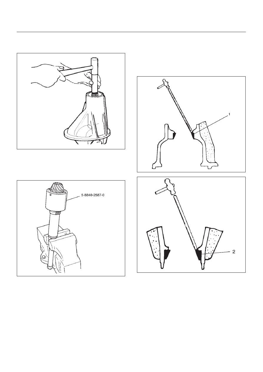
5. Remove side bearing by using remover
5–8840–2587–0 and adapter 5–8840–2576–0.
Select collet halves 44803 in remover kit
5–8840–2587–0 for side bearing removal and insert
is not required for this operation.
415RW041
6. Note the thickness and position of the shims then
remove adjust shim.
7. Remove the flange nut and washer by using pinion
flange holder 5–8840–0133–0 after raising up its
staked parts completely.
415RW040
4A2B–16
DIFFERENTIAL (REAR 244mm)
8. Removed flange assembly.
9. Remove the drive pinion assembly using a soft metal
rod and a hammer.
425RY005
10. Remove collapsible spacer.
11. Remove the inner bearing by using remover
5–8840–2587–0. Select insert 303174 and collet
halves 44803 in remover kit 5–8840–2587–0 for inner
bearing removal.
415RW042
12. Remove adjust shim.
13. Remove oil seal.
14. Remove oil seal slinger.
15. Remove outer bearing.
16. Remove the inner bearing outer race (1) and the outer
bearing outer race (2) by using a brass bar and a
hammer.
425RS014
425RS015
DIFFERENTIAL (REAR 244mm) 4A2B–17
Reassembly
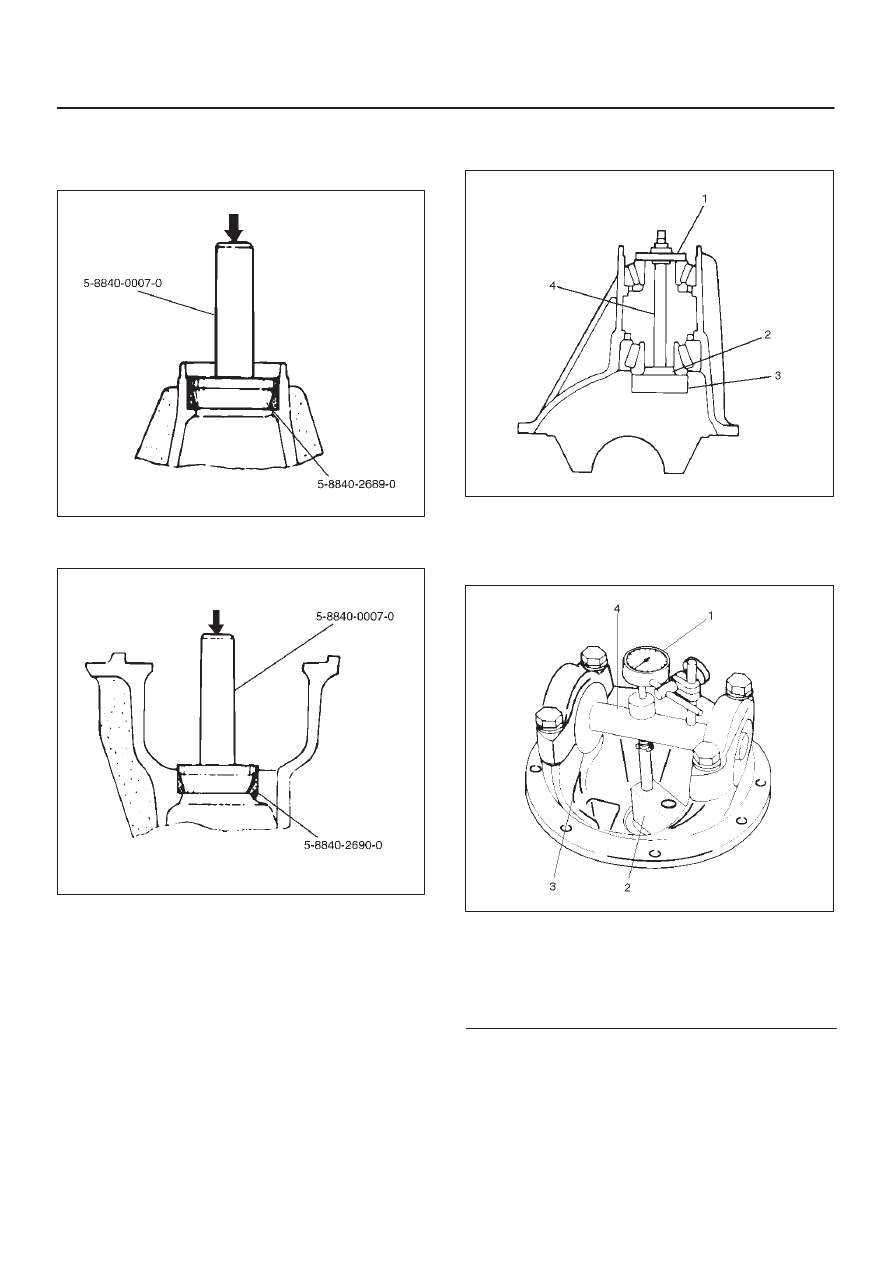
1. Install outer bearing outer race by using installer
5–8840–2689–0 and grip 5–8840–0007–0.
425RY00014
2. Install inner bearing outer race by using installer
5–8840–2690–0 and grip 5–8840–0007–0.
425RY00013
3. Adjust the drive pinion mounting distance as follows:
1. Apply gear oil to the inner and outer drive pinion
bearing. Clean the pinion setting gauge set.
Then install the gauge set together with the inner
and outer bearings.
Install gauge plate 5–8840–2678–0 (3), inner pilot
5–8840–2680–0 (2) ,bolt and nut 5–8840–0127–0
(4) and outer pilot 5–8840–2681–0 (1) through inner
and outer bearings.
2. Tighten the nut to the specified torque.
Torque: 2.3 N·m (23kg·cm/20 lb in)
425RW030
3. Clean the side bearing bores. Place discs and dial
indicator on to arbor, and place tool into position in
side bearing bores. Install and tighten the bearing
caps to the specified torque.
425RW031
Legend
(1) Dial Indicator: 5–8840–0126–0
(2) Gauge Plate: 5–8840–2678–0
(3) Disc (2 pcs.): 5–8840–2679–0
(4) Arbor: 5–8840–0128–0
4A2B–18
DIFFERENTIAL (REAR 244mm)
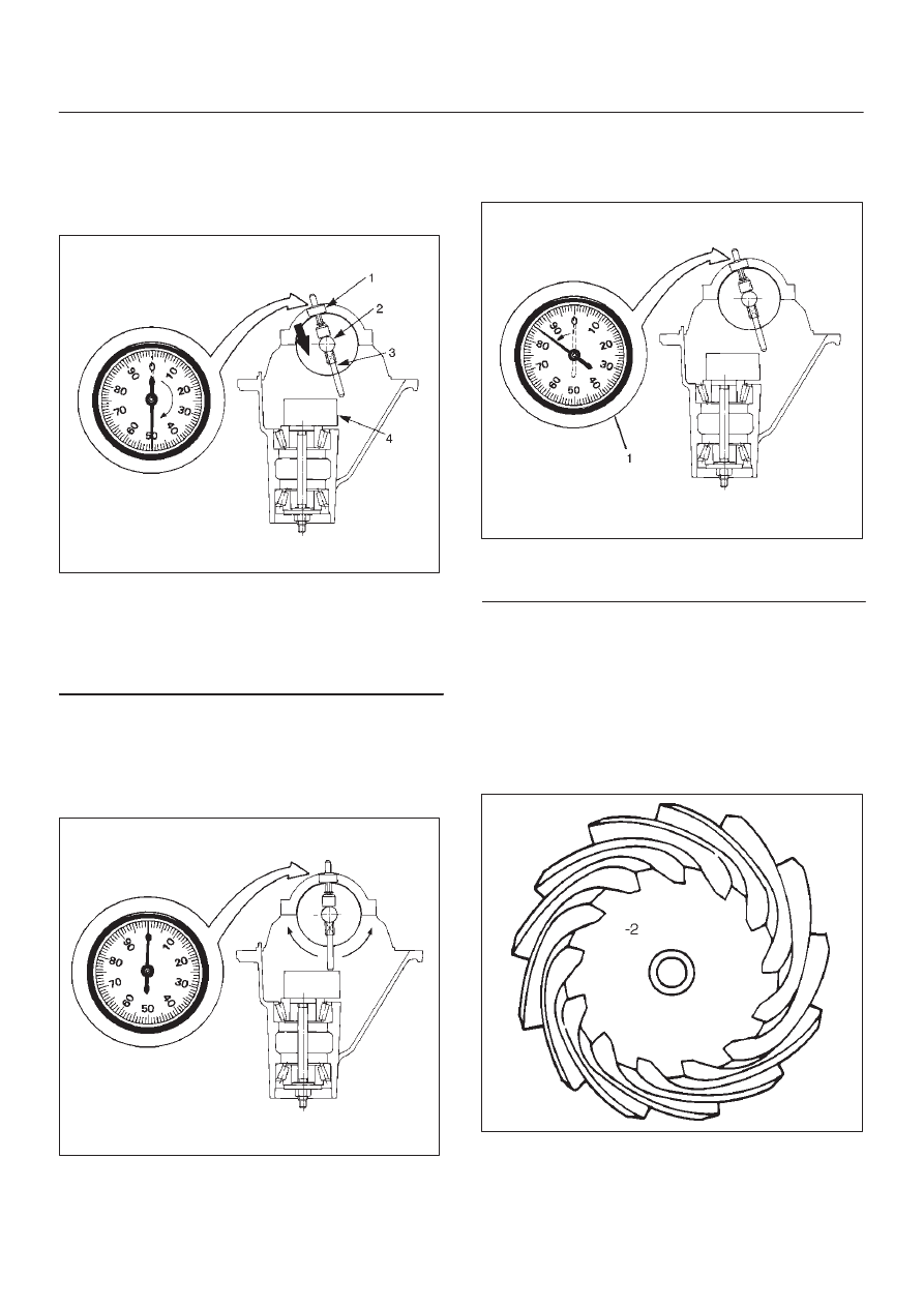
4. Set the dial indicator 5–8840–0126–0 to “0”.
Place it on the mounting post of the gauging arbor
with the contact button touching the indicator pad.
Force the dial indicator downward until the needle
has made a half turn clockwise. Tighten down the
dial indicator in this position.
425RS020
Legend
(1) Dial Indicator
(2) Ganging Arbor
(3) Plunger
(4) Gauge Plate
5. Position the plunger on the gauge plate. Move the
gauging arbor slowly back and forth and locate
the position at which the dial indicator shows the
greatest defection. At this point, once again set
the dial indicator to “0”. Repeat the procedure to
verify the “0” setting.
425RS021
6. After the ZERO setting is obtained, rotate the
gauging arbor until the dial indicator rod does not
touch the gauging plate. Record the number the
dial indicator needle points to.
425RS022
Legend
(1) Example=Dial indicator reading od 0.085
7. Record the pinion depth code on the head of the
drive pinion. The number indicates a necessary
change in the pinion mounting distance. A plus
number indicates the need for a greater mounting
distance (which can be achieved by decreasing
the shim thickness). A minus number indicates
the need for a smaller mounting distance (which
can be achieved by increasing the shim
thickness). If examination reveals pinion depth
code “0”, the pinion is “nominal”.
425RS023
Нет комментариевНе стесняйтесь поделиться с нами вашим ценным мнением.
Текст