Opel Frontera UBS. Service manual — part 2085
6A–74
ENGINE MECHANICAL
015RW002
Legend
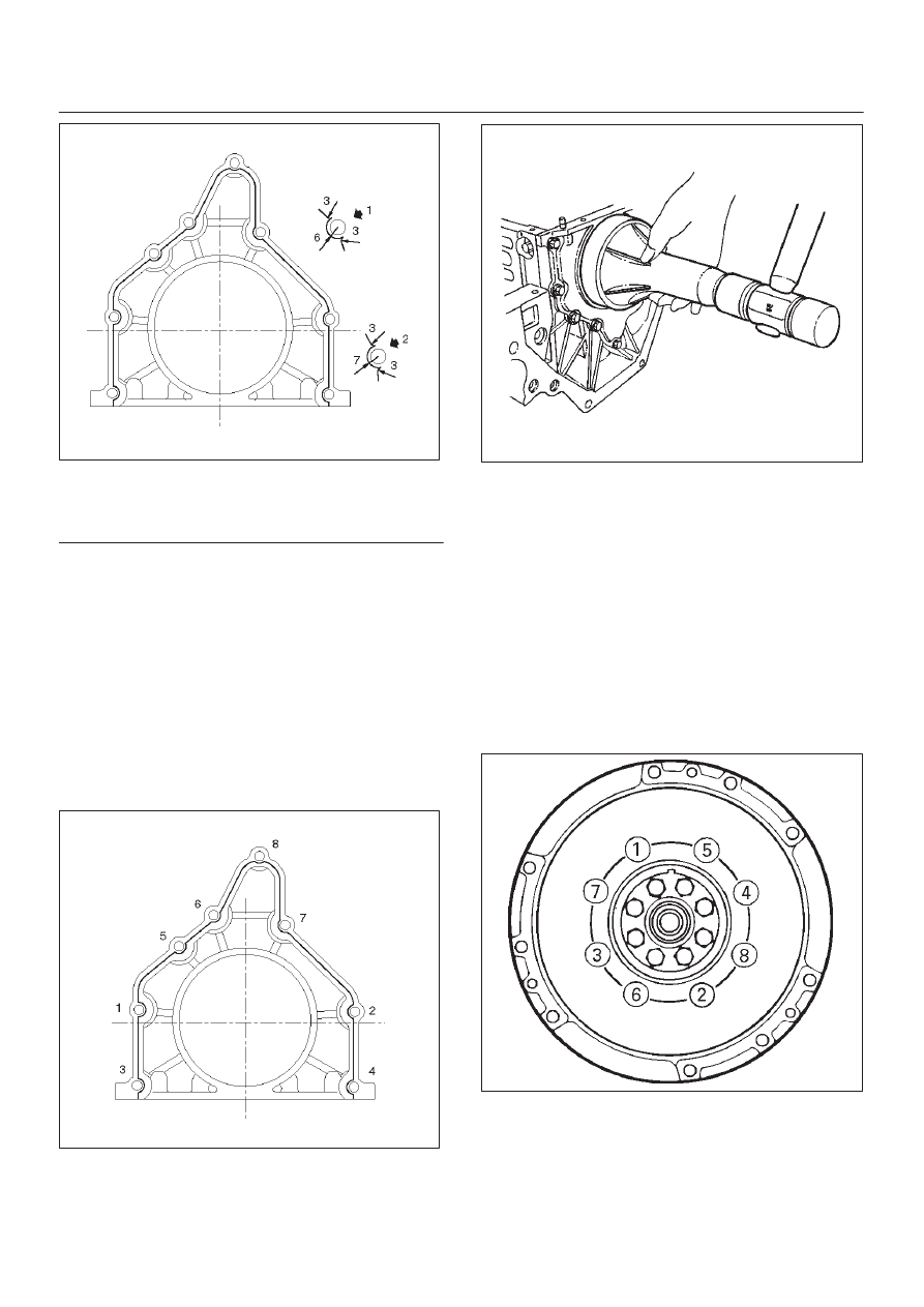
(1) Around Bolt Holes
(2) Around Dowel Pin
D
Apply engine oil to the oil seal lip.
D
Align the cylinder block dowel pin holes with the rear
retainer dowel pins.
D
Tighten the rear retainer fixing bolts. New bolts
should be used when installing rear retainer.
Torque: 18 N·m (1.8 Kg·m/13 lb ft)
NOTE: Be very careful not to disengage the oil seal garter
spring during installation of the rear retainer.
If the seal was removed from retainer for
replacement, apply engine oil to the oil seal lip and
install the oil seal using 5–8840–2286–0 oil seal
installer.
015RW001
015RS017
3. Flywheel (9)
1. Thoroughly clean and remove the oil from the
threads of crankshaft.
2. Remove the oil from the crankshaft and flywheel
mounting faces.
3. Mount the flywheel on the crankshaft and then
install the washer.
4. Hold the crankshaft to prevent from rotating then
install the bolts in the order shown to the specified
torque.
Torque: 54 N·m (5.5 Kg·m/40 lb ft)
NOTE: Do not reuse the bolt and do not apply oil or thread
lock to the bolt.
015RS018
6A–75
ENGINE MECHANICAL
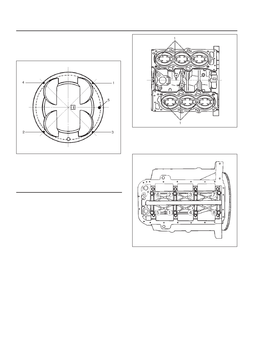
4. Piston and connecting rod assembly (8)
D
Apply engine oil to the cylinder bores, the
connecting rod bearings and the crankshaft pins.
Check to see that the piston ring end gaps are
correctly positioned.
015RS019
Legend
(1) No.1 Compression Ring
(2) No.2 Compression Ring
(3) Oil Ring Side Rail Upper
(4) Oil Ring Side Rail Lower
(5) Piston Front Mark
D
Insert the piston/connecting rod assemblies into
each cylinder with the piston ring compressor. The
front marks must be facing the front of the engine.
D
Match the numbered caps with the numbers on the
connecting rods. Align the punched marks on the
connecting rods and caps.
D
Apply engine oil to the threads and seating faces of
the nuts.
D
Tighten the nuts.
Torque: 54 N·m (5.5 Kg·m/40 lb ft)
After tightening the cap nuts, check to see that the
crankshaft rotates smoothly.
NOTE: Do not apply engine oil to the bearing back faces.
015RS020
5. Install oil gallery (7) and tighten the bolts in 2 steps, in
the order shown.
1st step: 29 N·m (3.0 Kg·m/22 lb ft)
2nd step: 55
°
∼
65
°
051RS009
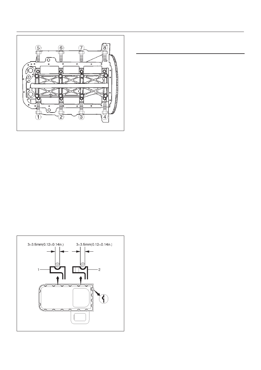
6. Cylinder block side bolts (6)
D
Tighten all the bolts to the specified torque in the
order shown.
NOTE: Do not apply engine oil to the crank case side
bolts.
Torque: 39 N·m (4.0 Kg·m/29 lb ft)
6A–76
ENGINE MECHANICAL
012RS001
7. Install oil pump assembly (5), refer to “Oil pump” in
this manual.
8. Install oil strainer and O-ring (4).
9. Install oil pipe and O-ring (3) and tighten the bolts.
Torque: 25 N·m (2.5 Kg·m/18 lb ft)
10. Install crankcase with oil pan (2).
1. Completely remove all residual sealant, lubricant
and moisture from the sealing surfaces. The
surfaces must be perfectly dry.
2. Apply a correct width bead of sealant (TB—
1207C or its equivalent) to the contact surfaces of
the oil pan. There must be no gaps in the bead.
3. The crankcase assembly must be installed within
5 minutes after sealant application to prevent
premature hardening of the sealant.
4. Tighten the bolts and nuts to the specified torque.
Torque : 10 N·m (1.0 Kg·m/89 lb in)
013RW010
Legend
(1) Portion Between Bolt Holes
(2) Bolt Hole Portion
11. Install cylinder head assembly, refer to “Cylinder
head” in this manual.
6A–77
ENGINE MECHANICAL
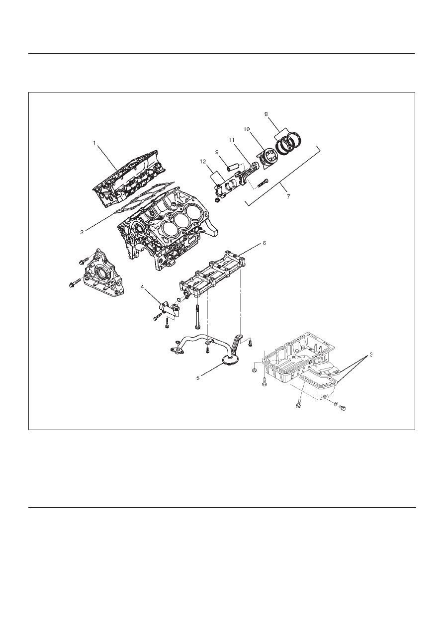
Piston and Connecting Rod
Piston, Connecting Rod and Associate Parts
015RW019
Legend
(1) Cylinder Head Assembly
(2) Cylinder Head Gasket
(3) Crankcase with Oil Pan
(4) Oil Pipe and O-Ring
(5) Oil Strainer and O-Ring
(6) Oil Gallery
(7) Piston and Connecting Rod Assembly
(8) Piston Ring
(9) Piston Pin
(10) Piston
(11) Connecting Rod
(12) Connecting Rod Cap
Disassembly
1. Remove cylinder head assembly (1). Refer to
“Cylinder Head Removal” in this manual.
2. Remove cylinder head gasket (2).
3. Remove crankcase with oil pan (3). Refer to“Oil Pan
and Crankcase” in this manual.
4. Remove oil pipe and O-ring (4).
5. Remove oil strainer and O-ring (5).
6. Remove oil gallery (6).
7. Remove connecting rod cap with connecting rod
lower bearing (12).
8. Remove piston and connecting rod assembly (7).
NOTE: Before removing piston and connecting rod
assembly, measure thrust clearance.
Нет комментариевНе стесняйтесь поделиться с нами вашим ценным мнением.
Текст