Opel Frontera UBS. Service manual — part 680
8D–150
WIRING SYSTEM
Rear Fog Light
WIRING SYSTEM
8D–151
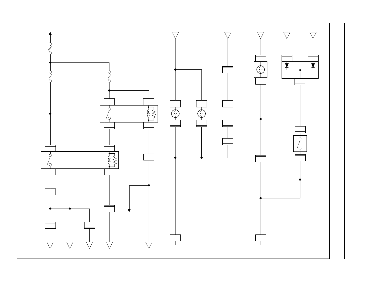
Circuit Diagram
5.0
W
3.0
W
FL-1 80A
MAIN
F-8 20A
FRT FOG
F-12 15A
TAIL ILLUMI
TAIL
RELAY
BATT.(+)
3
X-9
2
X-9
0.85
R/B
0.85
G/R
0.3
BR/R
0.3
BR/R
0.3
G
0.3
G
0.3
G
COMBINATION
SWITCH(8)
4
3
X-9
1
X-9
REAR
FOG
LIGHT
RELAY
REAR
FOG
LIGHT
-LH
X-22
X-22
X-22
H-27
X-22
H-15
1.25
BR/Y
1.25
Y/R
3.0
Y/R
0.85
BR/Y
1.25
BR/Y
1.25
BR/Y
0.5
BR/Y
14
4
1
2
A
B
C
D
A
1.25
BR/Y
1.25
BR/Y
0.5
BR/Y
1.25
BR/Y
1.25
BR/Y
B
R-13
3
R-13
1
1.25
B
1.25
B
1.25
B
1.25
B
REAR
FOG
LIGHT
-RH
R-12
3
R-12
1
TRAILER
HARNESS
CONNECTOR
H-44
2
H-33
8
H-44
4
H-33
20
R-4
BODY-RR
11
H-13
E
3
H-15
H-46
4
1
REAR
FOG
LIGHT
INDI-
CATOR
(METER)
LIGHTING
SW
C
D
E
I-10
B-12
10
B-39
1
B-39
3
B-39
DIODE
2
7
H-27
20
I-9
30
0.3
B
0.3
L
0.5
B
1.25
B
1.25
B
B-19
BODY-RH
1.25
B
B-12
2
D08RWA00
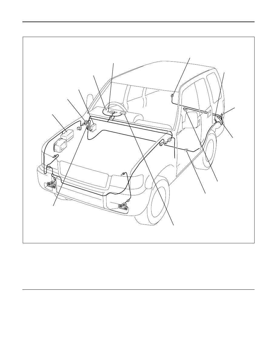
8D–152
WIRING SYSTEM
Parts Location
Legend
(1) Lighting Switch
(2) R-12
(3) R-4
(4) R-13
(5) H-33
(6) H-44
(7) H-46
(8) I-9
(9) B-19
(10) Relay and Fuse Box (X-9, X-22)
(11) H-13, H-15, H-27
(12) Fuse Box (B-39)
(13) I-10
6
7
8
9
10
11
12
13
1
2
3
4
5
D08RWA01
WIRING SYSTEM
8D–153
Headlight Leveling
General Description
The circuit consists of the headlight leveling SW and
headlight leveling actuators. The actuator is made
up of a motor, two relays and disk-type sensor. The
sensor rotates in accordance with the rotation of the
motor and stops the rotation of the motor at each
position corresponding to the levels 0 to 3.
Нет комментариевНе стесняйтесь поделиться с нами вашим ценным мнением.
Текст