Opel Frontera UBS. Service manual — part 1955
4B1–5
DRIVE LINE CONTROL SYSTEM (SHIFT ON THE FLY)
4. If vacuum is not applicable as much as –400mmHg,
and if there is resistance on the intake side, replace
with a new check valve.
VSV Assembly
Inspect the vehicle side harness as follows:
412RS071
Legend
(1) Grey
(2) Blue
1. Remove connector.
2. Shift transfer lever to 2H and start the engine.
NOTE: Do not move the vehicle while inspection.
3. Make sure that there is continuity in the vehicle side of
harness. If there is no continuity, check transfer shift
switch and wiring.
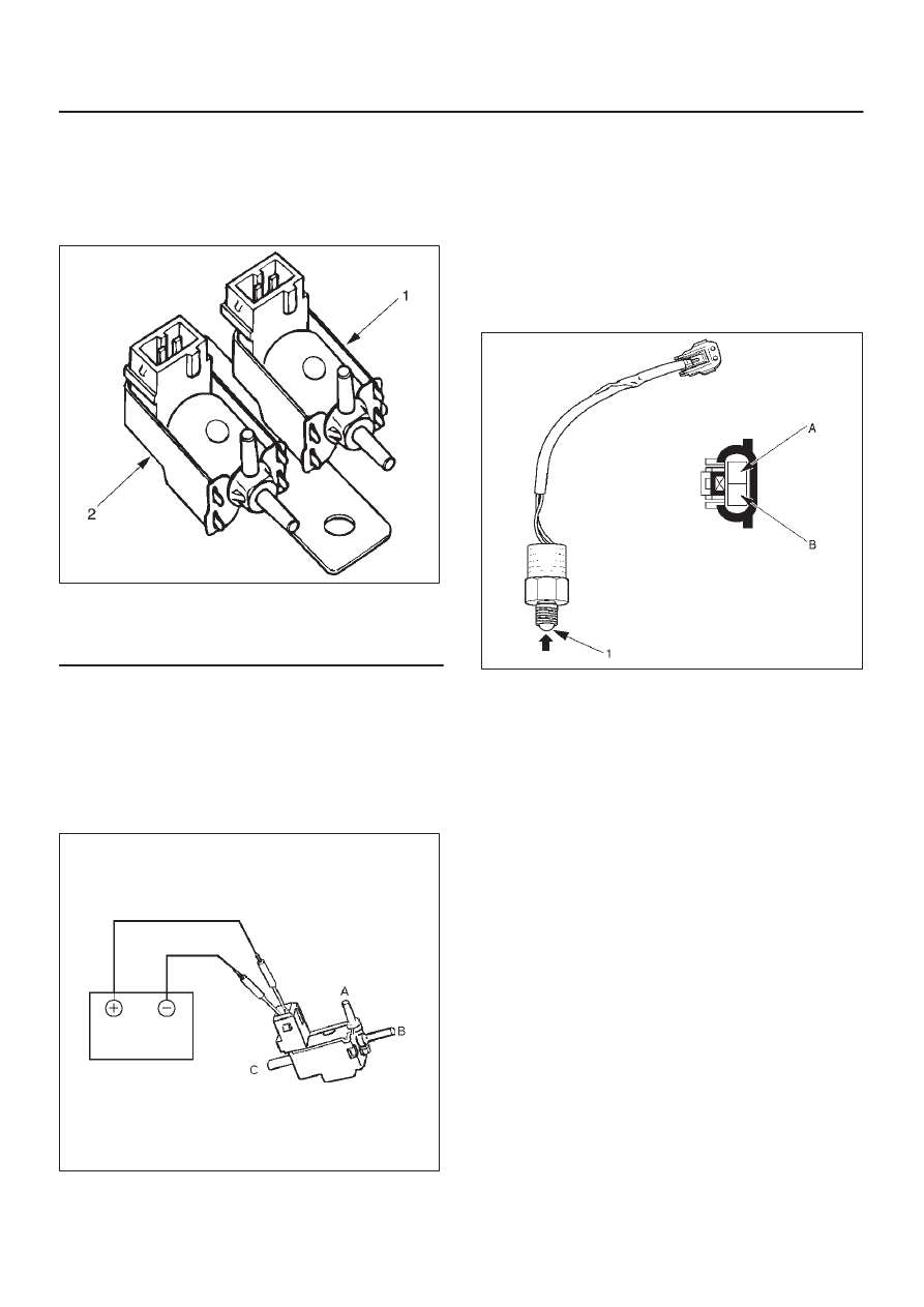
Inspect both VSVs as follows:
F04RS004
1. With battery not connected (Usual).
A–C:There is continuity
B:Closed
2. With battery connected
A – B:There is continuity
C:Closed
3. If 1) and 2) fail, replace with a new VSV.
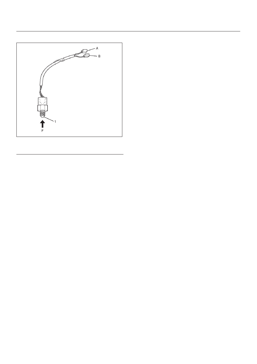
Axle Position Switch
412RS048
1. With ball (1) being free
A – B:There is continuity
2. With ball forced into the switch
A – B:No continuity
3. If 1) and 2) fail, replace with a new switch.
4B1–6 DRIVE LINE CONTROL SYSTEM (SHIFT ON THE FLY)
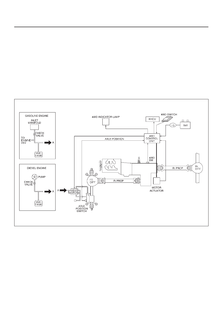
Transfer Position Switch
412RW040
Legend
(1) Ball
1. With ball being free.
A–B : There is continuity.
2. With ball forced into the switch.
A–B : No continuity.
3. If 1) and 2) fail, replace with a new switch.
4B1–7
DRIVE LINE CONTROL SYSTEM (SHIFT ON THE FLY)
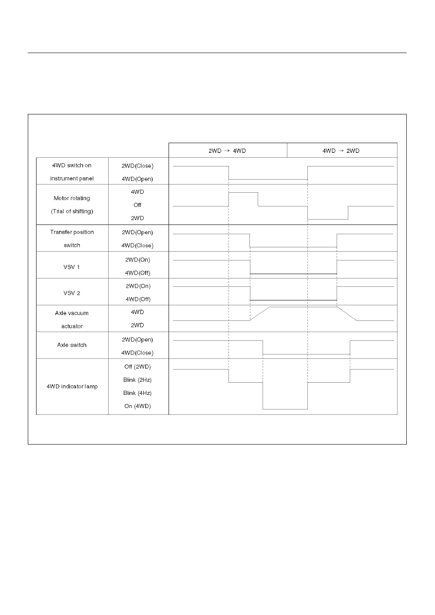
Shift on the Fly System (Push Button Type)
Outline of Shift on the Fly System (Push Button Type)
The shift on the fly system switches between 2 wheel
drive (2WD) and 4 wheel drive (4WD) electrically by
driver’s pressing the 4WD switch (push button type) on
instrument panel.
This system controls below operations. (Shifting between
“4H” and “4L” must be performed by transfer control lever
on the floor.)
1. Shifting the transfer front output gear (Connecting to,
and disconnecting from, front propeller shaft by motor
actuator).
2. Retrial of shifting the transfer front output gear.
3. Connecting front wheels to, and disconnecting them
from, the front axles by vacuum actuator.
4. Indicator on instrument panel.
5. 4WD out signal to other Electronic Hydraulic Control
Unit (If anti–lock brake system is equipped).
System Diagrams
412RW050
4B1–8 DRIVE LINE CONTROL SYSTEM (SHIFT ON THE FLY)
Normal Operation
The motor actuator mounted on transfer rear case is
driven by signal from 4WD switch on instrument panel.
After complete the connecting transfer front output gear
to, or disconnecting it from, front propeller shaft, condition
of the transfer position switch changes. The vacuum
solenoid valve (VSV) is driven by the signal from transfer
position switch and the vacuum actuator connects front
wheels to, or disconnect them from, front axles.
Time Chart of Shifting Under Normal Condition
F04RW002
Нет комментариевНе стесняйтесь поделиться с нами вашим ценным мнением.
Текст