Opel Frontera UBS. Service manual — part 1581
8D–2
WIRING SYSTEM
Diagnosis. . . . . . . . . . . . . . . . . . . . . . . . . . .
8D–268
Cruise Control . . . . . . . . . . . . . . . . . . . . . . . .
8D–274
General Description . . . . . . . . . . . . . . . . . .
8D–274
Circuit Diagram. . . . . . . . . . . . . . . . . . . . . .
8D–275
Parts Location . . . . . . . . . . . . . . . . . . . . . . .
8D–277
Diagnosis. . . . . . . . . . . . . . . . . . . . . . . . . . .
8D–281
Anti–Lock Brake System (ABS) . . . . . . . . . .
8D–286
General Description . . . . . . . . . . . . . . . . . .
8D–286
Circuit Diagram. . . . . . . . . . . . . . . . . . . . . .
8D–287
Parts Location . . . . . . . . . . . . . . . . . . . . . . .
8D–293
A/T Shift Lock . . . . . . . . . . . . . . . . . . . . . . . . .
8D–300
General Description . . . . . . . . . . . . . . . . . .
8D–300
Circuit Diagram. . . . . . . . . . . . . . . . . . . . . .
8D–301
Parts Location . . . . . . . . . . . . . . . . . . . . . . .
8D–302
Windshield Wiper/Washer . . . . . . . . . . . . . .
8D–305
General Description . . . . . . . . . . . . . . . . . .
8D–305
Circuit Diagram. . . . . . . . . . . . . . . . . . . . . .
8D–306
Parts Location . . . . . . . . . . . . . . . . . . . . . . .
8D–307
Diagnosis. . . . . . . . . . . . . . . . . . . . . . . . . . .
8D–310
Rear Wiper/Washer . . . . . . . . . . . . . . . . . . . .
8D–318
General Description . . . . . . . . . . . . . . . . . .
8D–318
Circuit Diagram. . . . . . . . . . . . . . . . . . . . . .
8D–319
Parts Location . . . . . . . . . . . . . . . . . . . . . . .
8D–321
Diagnosis. . . . . . . . . . . . . . . . . . . . . . . . . . .
8D–325
Headlight Wiper/Washer . . . . . . . . . . . . . . .
8D–331
General Description . . . . . . . . . . . . . . . . . .
8D–331
Circuit Diagram. . . . . . . . . . . . . . . . . . . . . .
8D–332
Parts Location . . . . . . . . . . . . . . . . . . . . . . .
8D–334
Diagnosis. . . . . . . . . . . . . . . . . . . . . . . . . . .
8D–338
Rear Defogger . . . . . . . . . . . . . . . . . . . . . . . .
8D–344
General Description . . . . . . . . . . . . . . . . . .
8D–344
Circuit Diagram. . . . . . . . . . . . . . . . . . . . . .
8D–345
Parts Location . . . . . . . . . . . . . . . . . . . . . . .
8D–346
Diagnosis. . . . . . . . . . . . . . . . . . . . . . . . . . .
8D–349
Audio . . . . . . . . . . . . . . . . . . . . . . . . . . . . . . .
8D–352
General Description . . . . . . . . . . . . . . . . . .
8D–352
Circuit Diagram. . . . . . . . . . . . . . . . . . . . . .
8D–353
Parts Location . . . . . . . . . . . . . . . . . . . . . . .
8D–357
Cigarette Lighter and Digital Clock . . . . . . .
8D–361
General Description . . . . . . . . . . . . . . . . . .
8D–361
Circuit Diagram. . . . . . . . . . . . . . . . . . . . . .
8D–362
Parts Location . . . . . . . . . . . . . . . . . . . . . . .
8D–363
Power Door Mirror . . . . . . . . . . . . . . . . . . . .
8D–366
General Description . . . . . . . . . . . . . . . . . .
8D–366
Circuit Diagram. . . . . . . . . . . . . . . . . . . . . .
8D–367
Parts Location . . . . . . . . . . . . . . . . . . . . . . .
8D–370
Diagnosis. . . . . . . . . . . . . . . . . . . . . . . . . . .
8D–375
Anti–Theft System with Keyless Entry . . . .
8D–382
Circuit Diagram. . . . . . . . . . . . . . . . . . . . . .
8D–383
Parts Location . . . . . . . . . . . . . . . . . . . . . . .
8D–394
Diagnosis. . . . . . . . . . . . . . . . . . . . . . . . . . .
8D–401
Meter and Warning/Indicator Light . . . . . .
8D–414
General Description . . . . . . . . . . . . . . . . . .
8D–414
Circuit Diagram. . . . . . . . . . . . . . . . . . . . . .
8D–415
Parts Location . . . . . . . . . . . . . . . . . . . . . . .
8D–433
Diagnosis. . . . . . . . . . . . . . . . . . . . . . . . . . .
8D–449
A/T Shift Indicator . . . . . . . . . . . . . . . . . . . . .
8D–468
General Description . . . . . . . . . . . . . . . . . .
8D–468
Circuit Diagram. . . . . . . . . . . . . . . . . . . . . .
8D–469
Parts Location . . . . . . . . . . . . . . . . . . . . . . .
8D–471
Heater and Air Conditioning . . . . . . . . . . . .
8D–475
General Description . . . . . . . . . . . . . . . . . .
8D–475
Circuit Diagram. . . . . . . . . . . . . . . . . . . . . .
8D–476
Parts Location . . . . . . . . . . . . . . . . . . . . . . .
8D–478
Sun Roof . . . . . . . . . . . . . . . . . . . . . . . . . . . . .
8D–488
General Description . . . . . . . . . . . . . . . . . .
8D–488
Circuit Diagram. . . . . . . . . . . . . . . . . . . . . .
8D–489
Parts Location . . . . . . . . . . . . . . . . . . . . . . .
8D–490
Diagnosis. . . . . . . . . . . . . . . . . . . . . . . . . . .
8D–493
Seat Heater . . . . . . . . . . . . . . . . . . . . . . . . . . .
8D–497
General Description . . . . . . . . . . . . . . . . . .
8D–497
Circuit Diagram. . . . . . . . . . . . . . . . . . . . . .
8D–498
Parts Location . . . . . . . . . . . . . . . . . . . . . . .
8D–499
Diagnosis. . . . . . . . . . . . . . . . . . . . . . . . . . .
8D–502
Power Seat . . . . . . . . . . . . . . . . . . . . . . . . . . .
8D–504
General Description . . . . . . . . . . . . . . . . . .
8D–504
Circuit Diagram. . . . . . . . . . . . . . . . . . . . . .
8D–505
Parts Location . . . . . . . . . . . . . . . . . . . . . . .
8D–507
Diagnosis. . . . . . . . . . . . . . . . . . . . . . . . . . .
8D–511
Shift on the Fly System . . . . . . . . . . . . . . . .
8D–517
Circuit Diagram. . . . . . . . . . . . . . . . . . . . . .
8D–518
Parts Location . . . . . . . . . . . . . . . . . . . . . . .
8D–520
Torque on Demand (TOD) . . . . . . . . . . . . . .
8D–542
Circuit Diagram. . . . . . . . . . . . . . . . . . . . . .
8D–543
Parts Location . . . . . . . . . . . . . . . . . . . . . . .
8D–546
Supplemental Restraint System (SRS)–
AIR BAG . . . . . . . . . . . . . . . . . . . . . . . . . . . . .
8D–547
General Description . . . . . . . . . . . . . . . . . .
8D–547
Circuit Diagram. . . . . . . . . . . . . . . . . . . . . .
8D–548
Parts Location . . . . . . . . . . . . . . . . . . . . . . .
8D–552
Connector List . . . . . . . . . . . . . . . . . . . . . . . .
8D–554
WIRING SYSTEM
8D–3
Service Precaution
WARNING: THIS VEHICLE HAS A SUPPLEMENTAL
RESTRAINT SYSTEM (SRS). REFER TO THE SRS
COMPONENT AND WIRING LOCATION VIEW IN
ORDER TO DETERMINE WHETHER YOU ARE
PERFORMING SERVICE ON OR NEAR THE SRS
COMPONENTS OR THE SRS WIRING. WHEN YOU
ARE PERFORMING SERVICE ON OR NEAR THE SRS
COMPONENTS OR THE SRS WIRING, REFER TO
THE SRS SERVICE INFORMATION. FAILURE TO
FOLLOW WARNINGS COULD RESULT IN POSSIBLE
AIR BAG DEPLOYMENT, PERSONAL INJURY, OR
OTHERWISE UNNEEDED SRS SYSTEM REPAIRS.
CAUTION: Always use the correct fastener in the
proper location. When you replace a fastener, use
ONLY the exact part number for that application.
ISUZU will call out those fasteners that require a
replacement after removal. ISUZU will also call out
the fasteners that require thread lockers or thread
sealant. UNLESS OTHERWISE SPECIFIED, do not
use supplemental coatings (Paints, greases, or other
corrosion inhibitors) on threaded fasteners or
fasteners joint interfaces. Generally, such coatings
adversely affect the fastener torque and the joint
clamping force, and may damage the fasteners.
When you install fasteners, use the correct
tightening sequence and specifications. Following
these instructions can help you avoid damage to
parts and systems.
8D–4
WIRING SYSTEM
The chassis electrical system is a 12–volt system with a
negative ground polarity.
Wire size are appropriate to respective circuits, and
classified by color. (The classification of harnesses by
color is shown on the circuit diagram for ease of harness
identification.)
The wire size is determined by load capacity and the
length of wire required.
The vehicle harnesses are: body harness, chassis
harness, engine room harness, instrument harness,
transmission harness, engine ECGI harness, dome light
harness, door harness, rear body harness, tailgate
harness, SRS harness and battery cables.
The harnesses are protected either by tape or corrugated
tube, depending on harness location.
The circuit for each system consists of the power source,
wire, fuse, relay, switch, load parts and ground, all of
which are shown on the circuit diagram.
In this section, each electrical device is classified by
system.
For major parts shown on the circuit based on the circuit
diagram for each system, a summary, diagnosis of
troubles and inspection procedures are detailed.
Notes for Working on Electrical
Items
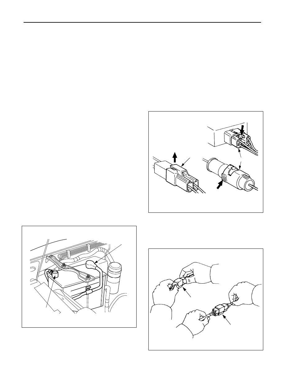
Disconnecting the Battery Cable
1. All switches should be in the “OFF” position.
2. Disconnect the battery ground cable (2).
3. Disconnect the battery positive cable (1).
CAUTION: It is important that the battery ground
cable be disconnected first. Disconnecting the
battery positive cable first can result in a short circuit.
Connecting the Battery Cable
Follow the disconnecting procedure in the reverse order.
CAUTION: Clean the battery terminal and apply a
light coat of grease to prevent terminal corrosion.
Disconnecting the Connector
Some connectors have a tang lock to hold the connectors
together during vehicle operation.
Some tang locks are released by pulling them towards
you (1).
Other tang locks are released by pressing them forward
(2).
Determine which type of tang lock is on the connector
being handled.
Firmly grasp both sides (male and female) of the
connector (3).
Release the tang lock and carefully pull the two halves of
the connector apart.
Never pull on the wires to separate the connectors (4).
2
1
General Description
1
2
3
4
WIRING SYSTEM
8D–5
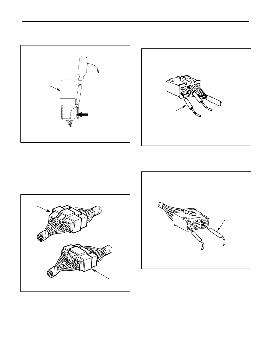
When removing the connector for relay (MR5B type) (5),
unfasten the tang lock of the connector by using a
screwdriver, then pull the relay out as shown in the figure.
Connecting the Connector
Firmly grasp both sides (male and female) of the
connectors. Be sure that both sides of the connectors are
aligned with each other.
Firmly but carefully push the two sides of the connectors
together until a distinct click is heard (2).
Do not connect them by force if they can not be connected
smoothly (1).
Connector Inspection
Use a circuit tester to check the connector for continuity.
Insert the test probes (1) from the connector wire side.
Never insert the circuit tester test probes (2) into the
connector open end to test the continuity.
Broken or open connector terminals will result.
5
1
2
1
2
Нет комментариевНе стесняйтесь поделиться с нами вашим ценным мнением.
Текст