Opel Frontera UBS. Service manual — part 1057
4C–45
DRIVE SHAFT SYSTEM
Universal Joint Reassembly
1. Install spider to flange yoke. Be sure to install the
spider by aligning the setting marks made during
disassembly.
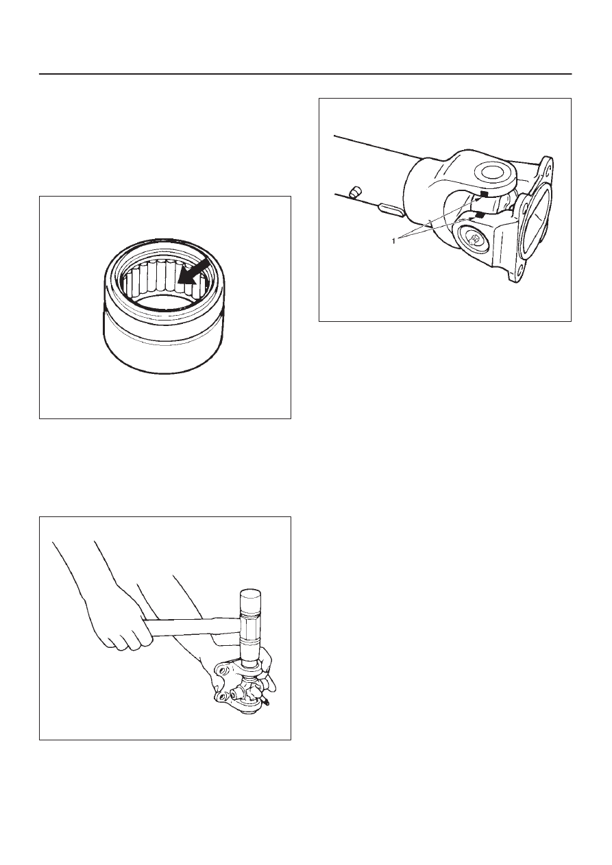
2. Apply a molybdenum–disulfide grease or a
multi–purpose type grease NLGI No. 2 to inside of the
bearing cap.
Grease Amount: Approx. 1.2 g (0.042 oz)
401RS011
3. Using either a mallet (or copper hammer) or a press,
install the needle roller bearing into the yoke so that
the snap ring can be installed in its groove.
CAUTION: The needle roller bearing cannot be
installed smoothly if it is set at an incorrect angle
with the flange and excessive hammering will
damage the needle roller bearing.
401RS012
4. Align setting marks (1) and join the yokes.
401RS028
5. Install snap ring.
NOTE: Discard used snap rings and install new ones.
When the bearing cap is in position, select and attach a
snap ring of suitable thickness so that the end play of the
spider pin is held within 0.1 mm (0.004 in).
Snap ring thickness and Identification color
1.5 mm (0.059 in); Blue
1.53 mm (0.060 in); White
1.59 mm (0.063 in); Yellow
1.62 mm (0.064 in); Green
1.68 mm (0.066 in); Not colored
NOTE: Be sure to use snap rings of the same thickness
on both sides.
4C–46
DRIVE SHAFT SYSTEM
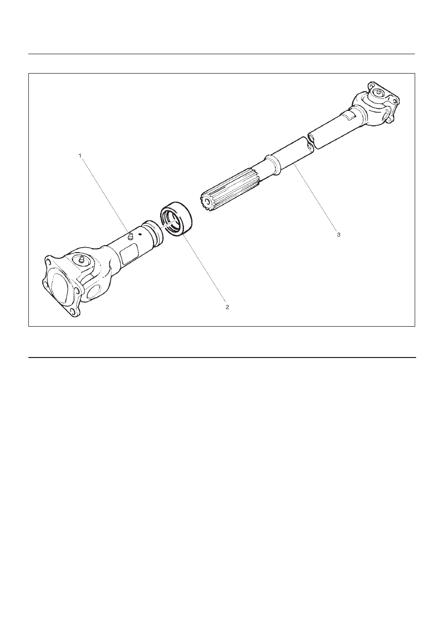
Reassembly (Except TOD 4
×
4)
401RW057
Legend
(1) Sleeve Yoke
(2) Seal
(3) Tube Assembly
1. Discard used seal and install new one.
2. Align the alignment marks and install tube assembly
to sleeve yoke.
4C–47
DRIVE SHAFT SYSTEM
Main Data and Specifications
General Specifications
Engine
6VE1 (3.5L)
6VD1 (3.2L)
4JX1 (3.0L)
4JG2 (3.1L)
Transmission
M/T
A/T
A/T
with
TOD
M/T
A/T
A/T
with
TOD
M/T
A/T
M/T
A/T
Construction
Hollow steel tube
with yoke and
spider type
universal joint
Hollow
steel
tube
with
consta
nt
velocity
joints
Hollow steel tube
with yoke and
spider type
universal joint
Hollow
steel
tube
with
consta
nt
velocity
joints
Hollow steel tube with yoke and
spider type universal joint
Outside
diameter
40.0mm (1.57 in)
Length
559mm
(22.01in)
559mm
(22.01in)
577mm
(22.72in)
393mm
(15.47in)
559mm
(22.01in)
577mm
(22.72in)
627mm
(24.69in)
627mm
(24.69in)
421mm
(16.57in)
627mm
(24.69in)
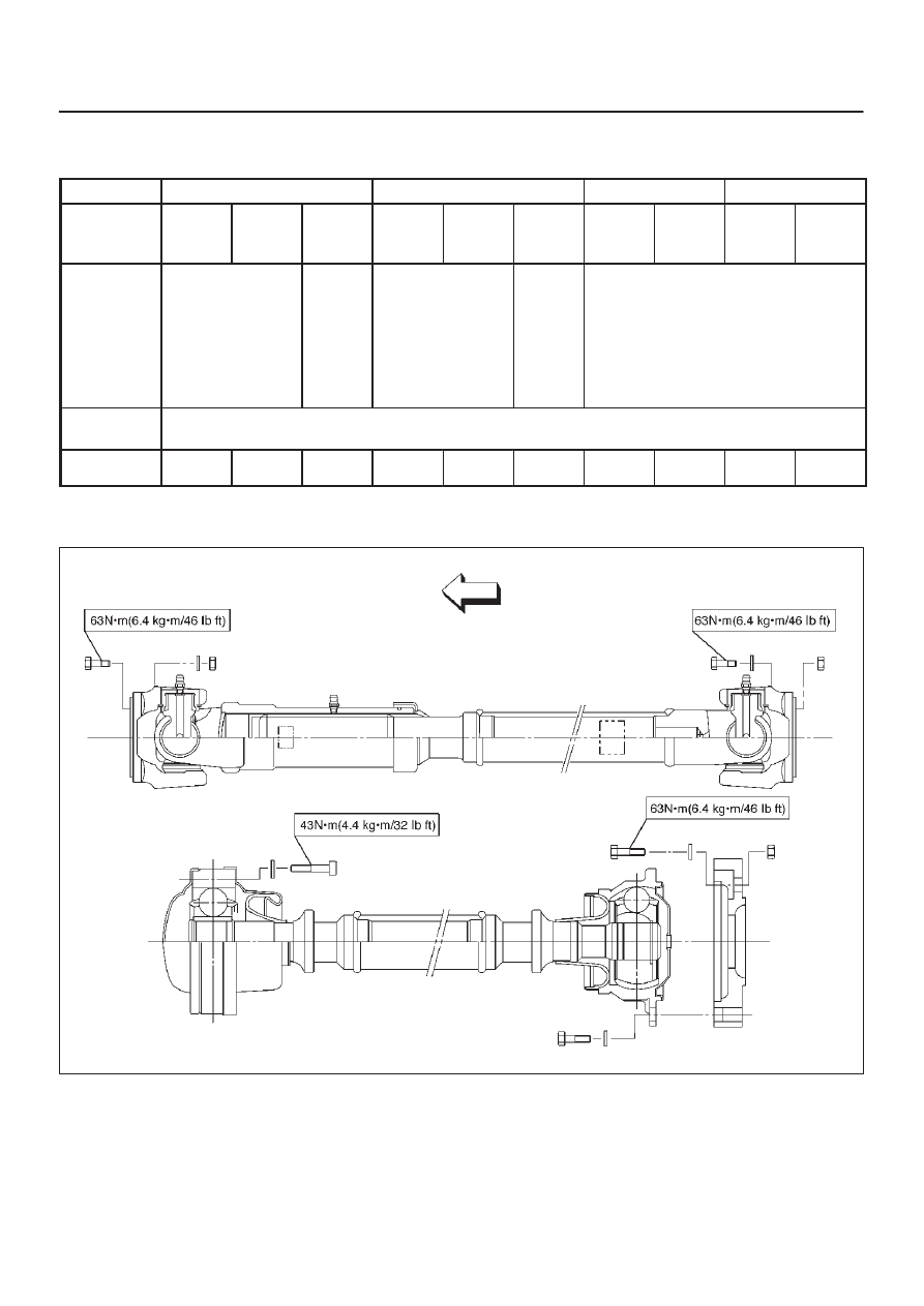
Torque Specifications
E04RW021
4C–48
DRIVE SHAFT SYSTEM
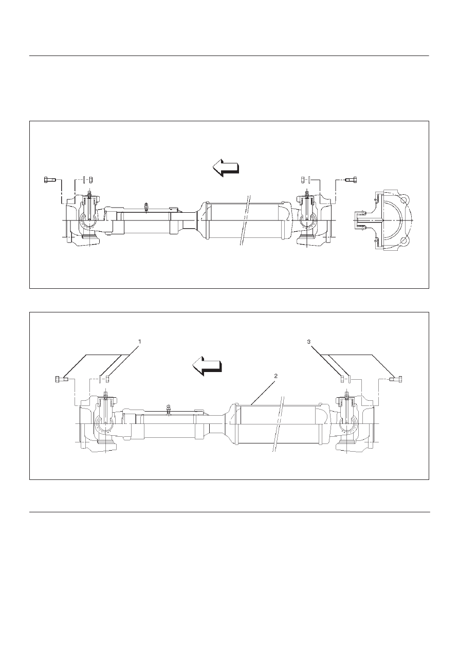
Rear Propeller Shaft
General Description
Since the propeller shaft is balanced carefully, welding or
any other modifications are not permitted.
Alignment marks should be applied to each propeller
shaft before removal.
401RW003
Rear Propeller Shaft and Associated Parts
401RW059
Legend
(1) Bolt, Nut and Washer
(2) Rear Propeller Shaft
(3) Bolt, Nut and Washer
Нет комментариевНе стесняйтесь поделиться с нами вашим ценным мнением.
Текст