Opel Frontera UBS. Service manual — part 2529
7A–74
AUTOMATIC TRANSMISSION (4L30–E)
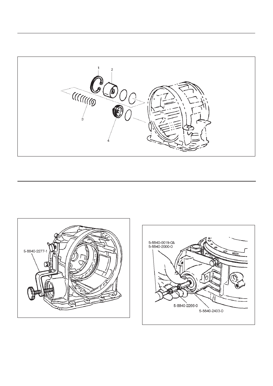
3–4 Accumulator Piston
Disassembled View
244RS005
Legend
(1) Snap Ring
(2) Cover
(3) Spring
(4) Piston Assembly
Disassembly
1. Install the 5–8840–2277–1 (J–38559–A) cover
compressor on adapter case.
D
Compress piston cover then remove snap ring.
242RW009
2. Install the 5–8840–2403–0 (J–41096) cover remover
and 5–8840–2266–0 (J–38584) adapter to center
hole of cover.
D
Use the 5–8840–0019–0 and 5–8840–2000–0
(J–23907) slide hammer to remove cover.
3. Remove spring and piston assembly.
242RW010
7A–75
AUTOMATIC TRANSMISSION (4L30–E)
Inspection And Repair
Visual Check:
If any damage, deformation or wear is found, replace the
damaged part.
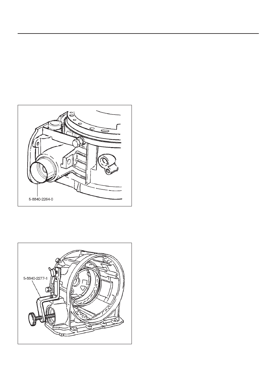
Reassembly
1. Place the 5–8840–2264–0 (J–38553) piston fitter into
adaptor case and push the piston into position, using
suitable diameter tube.
D
Remove the piston fitter.
244RW005
2. Install spring and cover.
3. Install snap ring, using the 5–8840–2277–1
(J–38559–A) compressor tool.
D
Install snap ring in groove.
D
Remove the compressor tool.
244RW006
7A–76
AUTOMATIC TRANSMISSION (4L30–E)
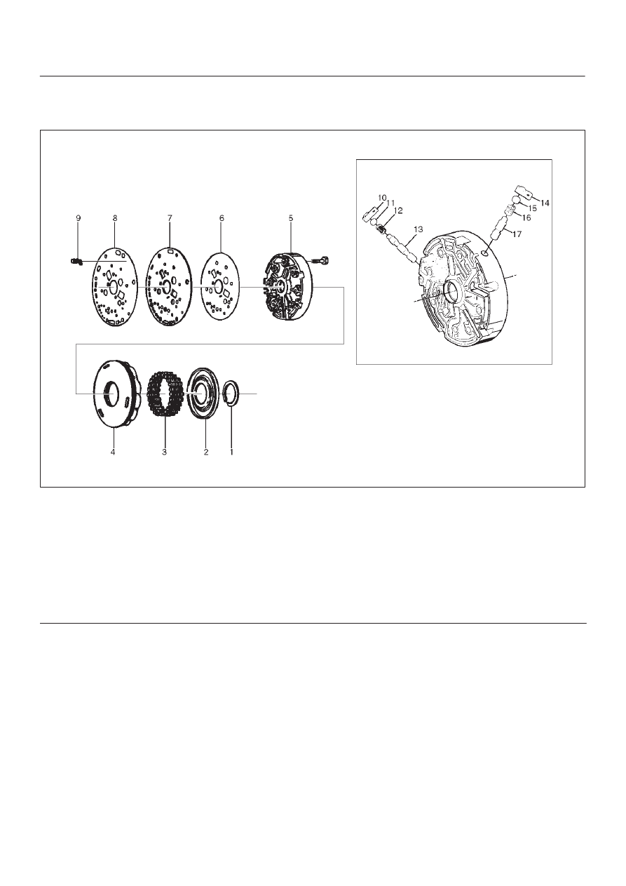
Reverse Clutch Piston And Center Support
Disassembled View
242RY001
Legend
(1) Retaining Ring
(2) Spring Seat
(3) Springs
(4) Piston Assembly
(5) Center Support
(6) Gasket
(7) Transfer Plate
(8) Gasket
(9) Restrictor
(10) Retainer Plate
(11) Plug
(12) Spring
(13) Overrun Lock Out Valve
(14) Retainer Plate
(15) Plug
(16) Spring
(17) Reverse Lock Out Control Valve
7A–77
AUTOMATIC TRANSMISSION (4L30–E)
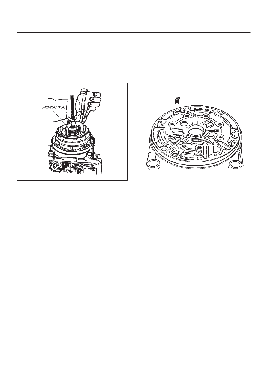
Disassembly
1. Install the 5–8840–0195–0 (J–23327) compressor
tool on spring seat, then compress the spring seat.
D
Remove retaining ring (1).
NOTE: Do not over–stress the springs and seat, as this
will cause damage to the spring seat.
D
Remove the compressor tool.
247RW006
2. Remove spring seat (2) and springs (3).
3. Remove piston assembly (4).
4. Remove 8 bolts from center support (5), then remove
center support (5) from adapter case.
5. Remove gasket transfer plate/outer support (6),
center support transfer plate (7), and gasket transfer
plate/adapter case (8).
6. Remove restrictor (9) from adapter case housing.
7. Remove retainer plate (10), plug (11), spring (12), and
overrun lock out valve (13) from center support (5).
8. Remove retainer plate (14), plug (15), spring (16) and
reverse lock out valve (17) from center support (5).
Inspection And Repair
Visual Check:
If any damage, deformation or wear is found, replace the
damaged part.
Reassembly
1. Install reverse lock out valve (17) and spring (16) to
center support.
NOTE: Ensure correct assembly of valve. The spring
should be located over the long small diameter end.
2. Install plug (15) and retainer plate (14).
3. Install overrun lock out valve (13) and spring (12) to
center support.
NOTE: Ensure correct assembly of valve. The spring
should be located over the long small diameter end.
4. Install plug (11) and retainer plate (10).
5. Place restrictor (9) in the lube overdrive channel in the
adapter case housing.
242RS005
6. Install gasket transfer plate/adapter case (8), center
support transfer plate (7), and gasket transfer
plate/center support (6).
7. Install center support (5) with 8 bolts.
Torque : 25 N
•
m (2.5 kg·m/18 Ib ft)
8. Install piston assembly (4) into center support (5).
9. Install twenty four springs (3), spring seat (2), and
retaining ring (1).
D
Install the 5–8840–0195–0 (J–23327) compressor
and compress spring seat (2) and springs (3), then
seat snap ring (1) in groove.
D
Remove the tool.
Нет комментариевНе стесняйтесь поделиться с нами вашим ценным мнением.
Текст