Opel Frontera UBS. Service manual — part 1123
6A–19
ENGINE MECHANICAL
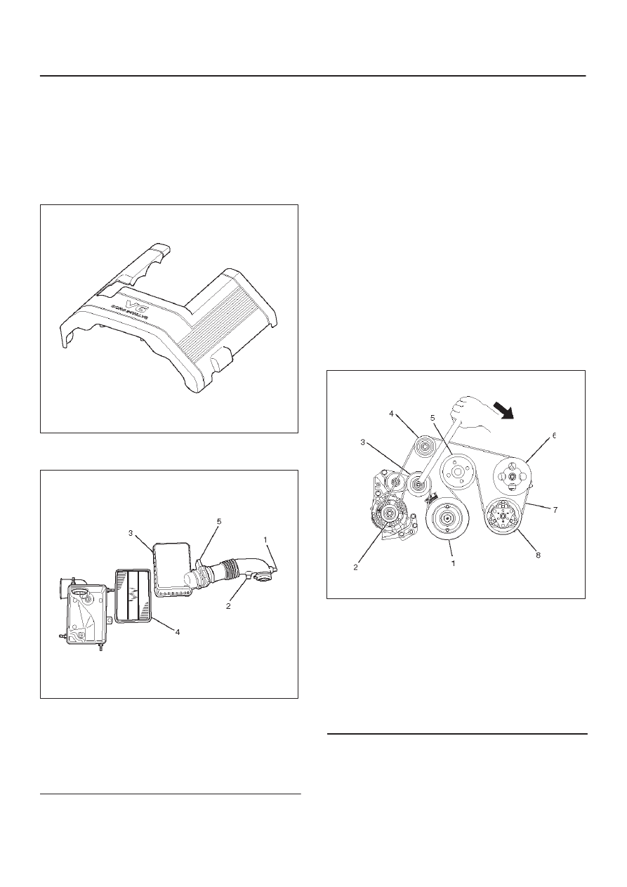
Legend
(1) Crankshaft Pulley
(2) Generator
(3) Auto Tensioner
(4) Idle Pulley
(5) Cooling Fan Pulley
(6) Power Steering Oil Pump
(7) Drive Belt
(8) Air Conditioner Compressor
12. Remove power steering oil pump pulley.
13. Remove fan pulley and bracket assembly.
14. Remove idle pulley assembly.
15. Remove auto tensioner assembly.
16. Remove crankshaft pulley using 5–8840–0133–0
crankshaft holder.
17. Remove timing belt covers from the right bank side to
the left bank side in order.
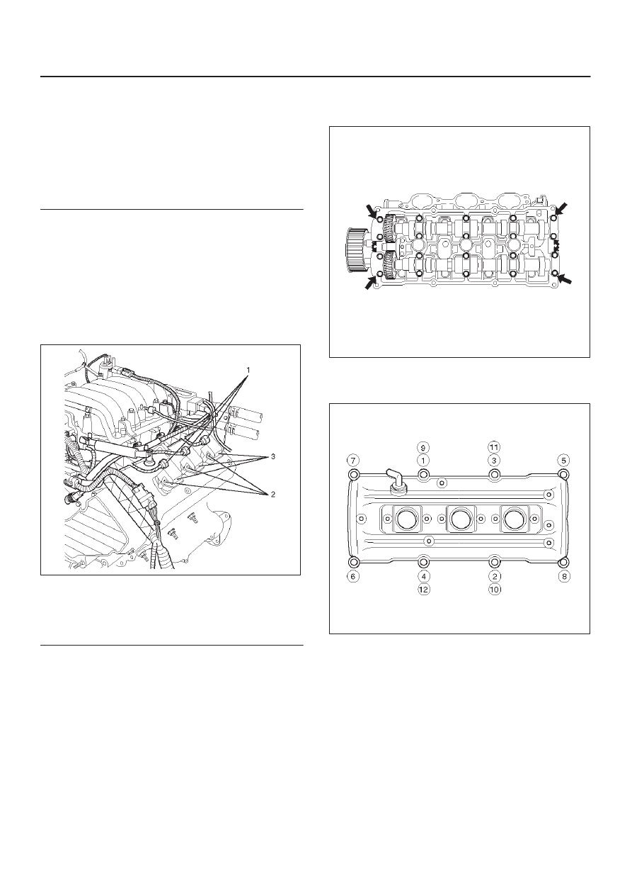
18. Remove ignition coil assemblies for the left side bank.
060RW018
Legend
(1) Ignition Coil Connectors
(2) Bolts
(3) Ignition Coil Assemblies
19. Remove cylinder head cover assembly.
Installation
1. Install cylinder head cover.
D
Clean the sealing surface of cylinder head and
cylinder head cover to remove oil and sealing
materials completely.
D
Apply sealant (TB-1207B or equivalent) of bead
diameter 2-3 mm at eight place of arched area of
camshaft bracket on front and rear sides.
D
The cylinder head cover must be installed within 5
minutes after sealant application to prevent
premature hardening of sealant.
014RW144
D
Tighten bolts to the specified torque.
Torque : 9 N·m (0.9 Kg·m/78 lb in)
010RW008
2. Install ignition coil assemblies and tighten the fixing
bolts to the specified torque.
Torque : 4 N·m (0.4 Kg·m/35 lb in)
3. Install timing belt covers from left bank side to right
bank side, and tighten the fixing bolts and nut to the
specified torque.
Torque : 19 N·m (1.9 Kg·m/14 lb ft)
4. Install crankshaft pulley and tighten the fixing bolt
using 5–8840–0133–0 crankshaft holder to the
specified torque.
Torque : 167 N·m (17.0 Kg·m/123 lb ft)
6A–20
ENGINE MECHANICAL
5. Install auto tensioner assembly and tighten the fixing
bolts to the specified torque.
Torque :
Shorter Bolt : 20 N·m (2.0 Kg·m/14 lb ft)
Longer Bolt : 39 N·m (4.0 Kg·m/29 lb ft)
6. Install idle pulley and bracket assembly and tighten
the fixing bolt to the specified torque.
Torque : 52 N·m (5.3 Kg·m/38 lb ft)
7. Install fan pulley and bracket assembly and tighten
the fixing bolts and nut to the specified torque.
Torque : 22 N·m (2.2 Kg·m/16 lb ft)
8. Install power steering oil pump pulley and tighten the
fixing bolt to the specified torque.
Torque : 78 N·m (8.0 Kg·m/58 lb ft)
9. Install drive belt by pushing down the auto tensioner
using spanner as shown in the removal step of drive
belt.
10. Install cooling fan and clutch assembly and tighten
the fixing bolts to the specified torque.
Torque : 10 N·m (1.0 Kg·m/87 lb in)
11. Install upper fan guide and clip both side and tighten
the fixing bolts to the specified torque.
Torque : 4 N·m (0.4 Kg·m/35 lb in)
12. Install engine harness and tighten the fixing bolts of
the retaining clip and bracket to the specified torque.
Torque : 4 N·m (0.4 Kg·m/35 lb in)
13. Connect radiator upper and lower hoses and clip
them securely.
14. Connect vacuum hoses of those which were
disconnected in the removal step.
15. Connect wiring connectors and bonding cable of
those which were disconnected in the removal step.
16. Install air cleaner element and air cleaner duct
assembly, and clip the both end securely.
17. Connect MAF sensor connector, IAT sensor
connector and PCV hose.
18. Install engine cover mating with the dowels.
6A–21
ENGINE MECHANICAL
Cylinder Head Cover RH
Removal
1. Disconnect battery ground cable.
2. Remove battery from the vehicle.
3. Drain engine coolant from faucet bottom of radiator.
4. Remove engine cover from the dowels on the
common chamber.
F06RW018
5. Remove air cleaner duct assembly (3) and air cleaner
element (4).
130RW001
Legend
(1) Positive Crankcase Ventilation Hose Connector
(2) Intake Air Temperature Sensor
(3) Air Cleaner Duct Assembly
(4) Air Cleaner Element
(5) Mass Air Flow Sensor
NOTE: Disconnect the mass air flow (MAF) sensor
connector, intake air temperature (IAT) sensor connector,
and positive crankcase ventilation (PCV) hose before
hand the air cleaner duct assembly is removed.
6. Disconnect following wiring connectors and bonding
cable:
D
Exhaust Gas Recirculation (EGR) valve
D
Fuel injectors for right bank
D
Ignition coils for right bank
D
Bonding cable
D
Othres as necessitated
7. Disconnect radiator upper and lower hoses.
8. Remove engine harness from the cylinder head
cover.
9. Remove the upper fan guide.
10. Remove cooling fan and clutch assembly.
11. Remove drive belt by pushing down the auto
tensioner using spanner as illustrated.
F06RW019
Legend
(1) Crankshaft Pulley
(2) Generator
(3) Auto Tensioner
(4) Idle Pulley
(5) Cooling Fan Pulley
(6) Power Steering Oil Pump
(7) Drive Belt
(8) Air Conditioner Compressor
12. Remove fan pulley and bracket assembly.
13. Remove idle pulley assembly.
14. Remove auto tensioner assembly.
15. Remove crankshaft pulley using 5–8840–0133–0
crankshaft holder.
6A–22
ENGINE MECHANICAL
16. Remove timing belt covers for right bank side.
17. Reomve timing belt covers for right bank side.
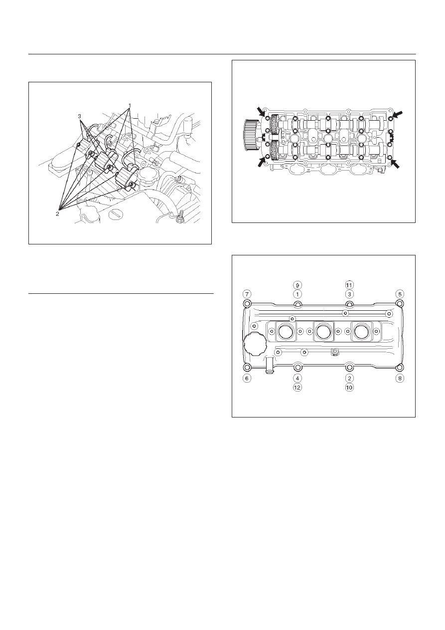
060RW001
Legend
(1) Ignition Coil Connectors
(2) Bolts
(3) Ignition Coil Assemblies
18. Remove ignition coil assemblies for the right side
bank.
19. Remove cylinder head cover assembly.
Installation
1. Install cylinder head cover.
D
Clean the sealing surface of cylinder head and
cylinder head cover to remove oil and sealing
materials completely.
D
Apply sealant (TB-1207B or equivalent) of bead
diameter 2-3 mm at eight place of arched area of
camshaft bracket on front and rear sides.
D
The cylinder head cover must be installed within 5
minutes after sealant application before the sealant
hardens.
014RW143
D
Tighten bolts in turn to the specified torque.
Torque : 8.8 N·m (0.9 Kg·m/78 lb in)
010RW007
2. Install ignition coil assemblies and tighten the fixing
bolts to the specified torque.
Torque : 4 N·m (0.4 Kg·m/35 lb in)
3. Install timing belt cover and tighten the fixing bolts and
nut to the specified torque.
Torque : 19 N·m (1.9 Kg·m/14 lb ft)
4. Install crankshaft pulley and tighten the fixing bolt
using 5–8840–0133–0 crankshaft holder to the
specified torque.
Torque : 167 N·m (17 Kg·m/123 lb ft)
5. Install auto tensioner assembly and tighten the fixing
bolts to the specified torque.
Torque :
Shorter Bolt : 20 N·m (2.0 Kg·m/14.8 lb ft)
Longer Bolt : 39 N·m (4.0 Kg·m/28.8 lb ft)
Нет комментариевНе стесняйтесь поделиться с нами вашим ценным мнением.
Текст