Opel Frontera UBS. Service manual — part 865
SUPPLEMENTAL RESTRAINT SYSTEM
9J–46
NOTE: SRS coil is a part of combination switch
assembly, which cannot be replaced separately.
Therefore, be sure not to remove the SRS coil from the
combination switch assembly.
15. Remove the snap ring.
16. Remove the cushion rubber.
17. Disconnect shift lock cable (A/T only).
18. Disconnect the starter switch harness connector
located base of steering column.
19. Remove steering lock cylinder assembly.
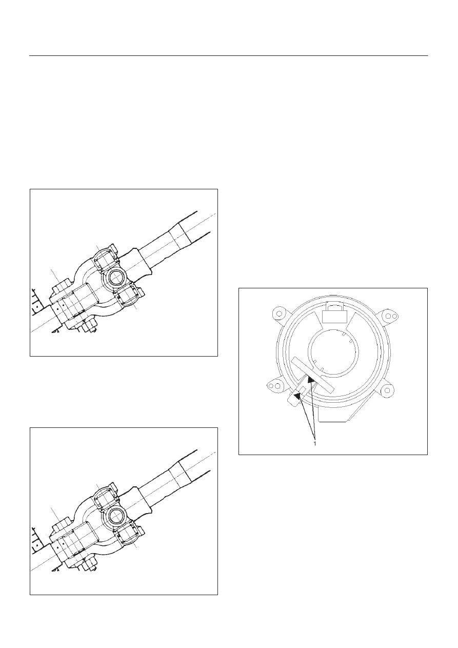
20. Apply a setting mark across the universal joint and
steering shaft to reassemble the parts in their original
position.
431RS013
21. Remove steering column assembly.
Installation
1. Install the steering column assembly and align the
setting marks on the universal joint and steering shaft
made during removal.
431RS013
2. Tighten the steering column fixing bolts (dash panel
side) to the specified torque.
Torque: 19 N·m (1.9 Kg·m/14 Ib ft)
3. Tighten the steering column fixing bolts (Pedal
bracket) to the specified torque.
Torque: 17 N·m (1.7 Kg·m/13 Ib ft)
4. Tighten the universal joint to the specified torque.
Torque: 25 N·m (2.6 Kg·m/18 Ib ft)
5. Install steering lock cylinder assembly.
6. Connect shift lock cable (For A/T)
7. Install cushion rubber.
8. Install snap ring.
9. Install the combination switch assembly with SRS
coil.
10. Connect the wiring harness connector located on the
base of steering column.
11. Turn the SRS coil counterclockwise to full, return
about 3 turns and align the neutral mark (1).
CAUTION: When turning the SRS coil
counterclockwise to full, stop turning if resistance is
felt. Forced further turning may damage to the cable
in the SRS coil.
826RW014
SUPPLEMENTAL RESTRAINT SYSTEM
9J–47
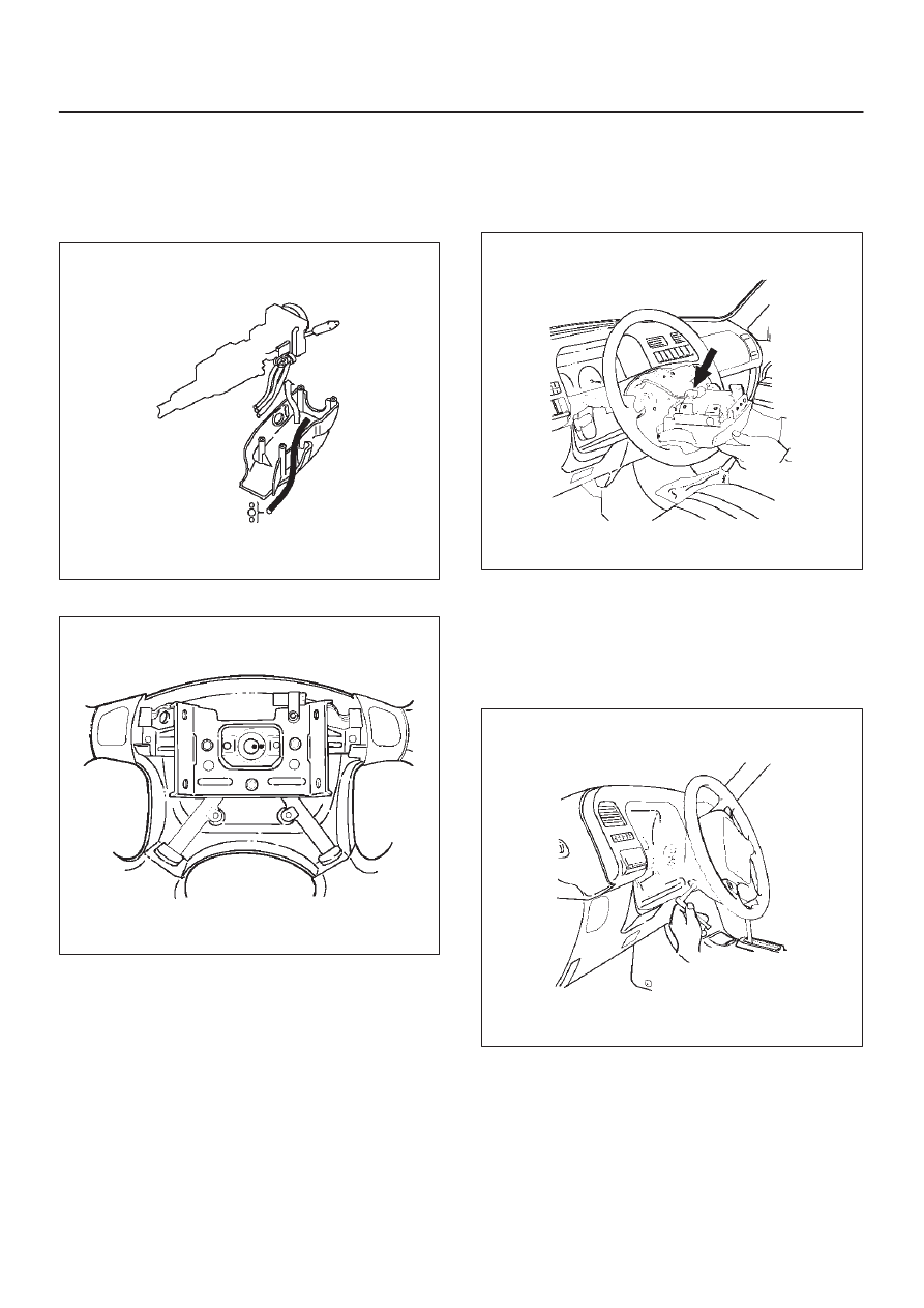
12. Install steering column cover.
CAUTION: When installing the steering column
cover, be sure to wire (through each harness) as
illustrated so that the harness starter switch,
combination switch and SRS coil may not catch
wiring.
825RS048
13. Install the steering wheel and align the setting marks.
430RS004
14. Tighten the steering wheel fixing nut to the specified
torque.
Torque: 34 N·m (3.5 Kg·m/25 Ib ft)
15. Connect horn lead.
16. Connect air bag wiring harness connector.
NOTE: Pass the lead wire through the tabs on the plastic
cover (wire protector) of air bag to prevent lead wire from
being pinched.
827RT009
17. Install air bag into steering wheel and tighten bolts to
specified sequence as shown in figure.
Torque: 8 N·m (0.8 Kg·m/69 Ib in)
CAUTION: Never use the air bag assembly from
another vehicle. Use only the air bag assembly
proper to the Trooper which is being repaired.
827RT008
18. Enable the SRS (Refer to “Enabling the SRS” in this
section).
SUPPLEMENTAL RESTRAINT SYSTEM
9J–48
Passenger Air Bag Assembly
Service Precautions
WARNING: SAFETY PRECAUTIONS MUST BE
FOLLOWED WHEN HANDLING A DEPLOYED AIR
BAG ASSEMBLY. AFTER DEPLOYMENT, THE AIR
BAG ASSEMBLY SURFACE MAY CONTAIN A SMALL
AMOUNT OF SODIUM HYDROXIDE, A BY–PRODUCT
OF THE DEPLOYMENT REACTION, THAT IS
IRRITATING TO THE SKIN AND EYES. MOST OF THE
POWER ON THE AIR BAG ASSEMBLY IS
HARMLESS. AS A PRECAUTION, WEAR GLOVES
AND SAFETY GLASSES WHEN HANDLING A
DEPLOYED AIR BAG ASSEMBLY, AND WASH YOUR
HANDS WITH MILD SOAP AND WATER
AFTERWARDS.
WARNING: WHEN CARRYING A LIVE AIR BAG
ASSEMBLY, MAKE SURE THE BAG AND TRIM
COVER ARE POINTED AWAY FROM YOU. NEVER
CARRY AIR BAG ASSEMBLY BY THE WIRES OR
CONNECTOR ON THE UNDERSIDE OF MODULE. IN
THE CASE OF AN ACCIDENTAL DEPLOYMENT, THE
BAG WILL THEN DEPLOY WITH MINIMAL CHANCE
OF INJURY. WHEN PLACING ALIVE AIR BAG
ASSEMBLY ON A BENCH OR OTHER SURFACE,
ALWAYS FACE BAG AND RIM COVER UP, AWAY
FROM THE SURFACE. NEVER REST A STEERING
COLUMN ASSEMBLY ON THE STEERING WHEEL
WITH THE AIR BAG ASSEMBLY FACE DOWN AND
COLUMN VERTICAL. THIS IS NECESSARY SO THAT
A FREE SPACE IS PROVIDED TO ALLOW THE AIR
BAG ASSEMBLY TO EXPAND IN THE UNLIKELY
EVENT OF ACCIDENTAL DEPLOYMENT.
OTHERWISE, PERSONAL INJURY COULD RESULT.
NOTE: IN THE EVENT DEPLOYMENT HAS
OCCURRED, INSPECT COIL ASSEMBLY WIRE FOR
ANY SIGNS OF SCORCHING, MELTING OR ANY
OTHER DAMAGE DUE TO EXCESSIVE HEAT. IF THE
COIL HAS BEEN DAMAGED, REPLACE IT.
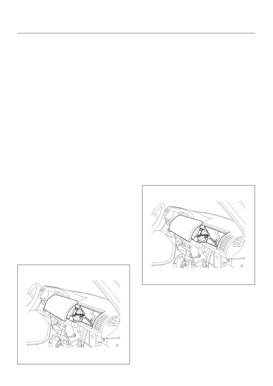
Removal
827RS001
1. Disable the SRS (Refer to “Disabling the SRS ” in this
section).
2. Remove gear control knob.
3. Remove front console assembly.
4. Remove rear console assembly and disconnect
harness connector.
5. Remove ECM and SDM cover.
6. Remove glove box assembly with lid.
7. Remove glove box cover.
8. Remove instrument panel assist side lower cover.
9. Disconnect engine hood opener lever.
10. Remove instrument panel door side lower cover.
11. Remove lower cluster with ashtray.
12. Remove meter cluster assembly and disconnect
harness connector.
13. Remove instrument panel lower center cover.
14. Disconnect passenger air bag assembly harness
connector.
15. Remove air bag assembly fixing bolts and nuts.
16. Remove passenger air bag assembly.
Installation
827RS001
1. Install passenger air bag assembly.
2. Install air bag assembly fixing bolts, nuts and tighten
to specified torque.
Torque: 6 N·m (0.6 Kg·m/52 Ib in)
3. Connect air bag assembly harness connector.
4. Install instrument panel lower center cover.
5. Install meter cluster assembly and connect harness
connector.
6. Install lower cluster with ashtray.
7. Install instrument panel door side lower cover.
8. Connect engine hood opener lever.
9. Install instrument panel assist side lower cover.
SUPPLEMENTAL RESTRAINT SYSTEM
9J–49
10. Install glove box cover.
11. Install glove box assembly with lid.
12. Install ECM and SDM cover.
13. Install rear console assembly and connect harness
connector.
14. Install front console assembly.
15. Install gear control knob.
16. Enable the SRS (Refer to “Enabling the SRS” in this
section).
Pretensioner Seat Belt (If so equipped)
Service Precaution
WARNING: WHEN PERFORMING SERVICE ON OR
AROUND THE PRETENSIONER SEAT BELT OR THE
PRETENSIONER SEAT BELT WIRING, FOLLOW THE
PROCEDURES LISTED BELOW TO TEMPORARILY
DISABLE THE PRETENSIONER SEAT BELT.
FAILURE TO FOLLOW PROCEDURES COULD
RESULT IN POSSIBLE THE PRETENSIONER SEAT
BELT DEPLOYMENT, PERSONAL INJURY OR
OTHERWISE UNNEEDED THE PRETENSIONER
SEAT BELT REPAIR.
AS A PRECAUTION, WEAR GLOVES AND SAFETY
GLASSES WHEN PERFORMING THE
PRETENSIONER SEAT BELT. WHEN DEPLOY A LIVE
PRETENSIONER SEAT BELT AT OUTSIDE THE
VEHICLE, DEPLOYMENT HARNESS SHALL REMAIN
SHORTED AND NOT BE CONNECTED TO A POWER
SOURCE UNTIL THE PRETENSIONER SEAT BELT IS
TO BE DEPLOYED. THE PRETENSIONER SEAT
BELT WILL IMMEDIATELY DEPLOY WHEN A POWER
SOURCE IS CONNECTED TO IT. CONNECTING THE
DEPLOYMENT HARNESS SHOULED ALWAYS BE
THE FINAL STEP IN THE PRETENSIONER SEAT
BELT DEPLOYMENT PROCEDURE. FAILURE TO
FOLLOW PROCEDURES IN THE ORDER LISTED
COULD RESULT IN PERSONAL INJURY.
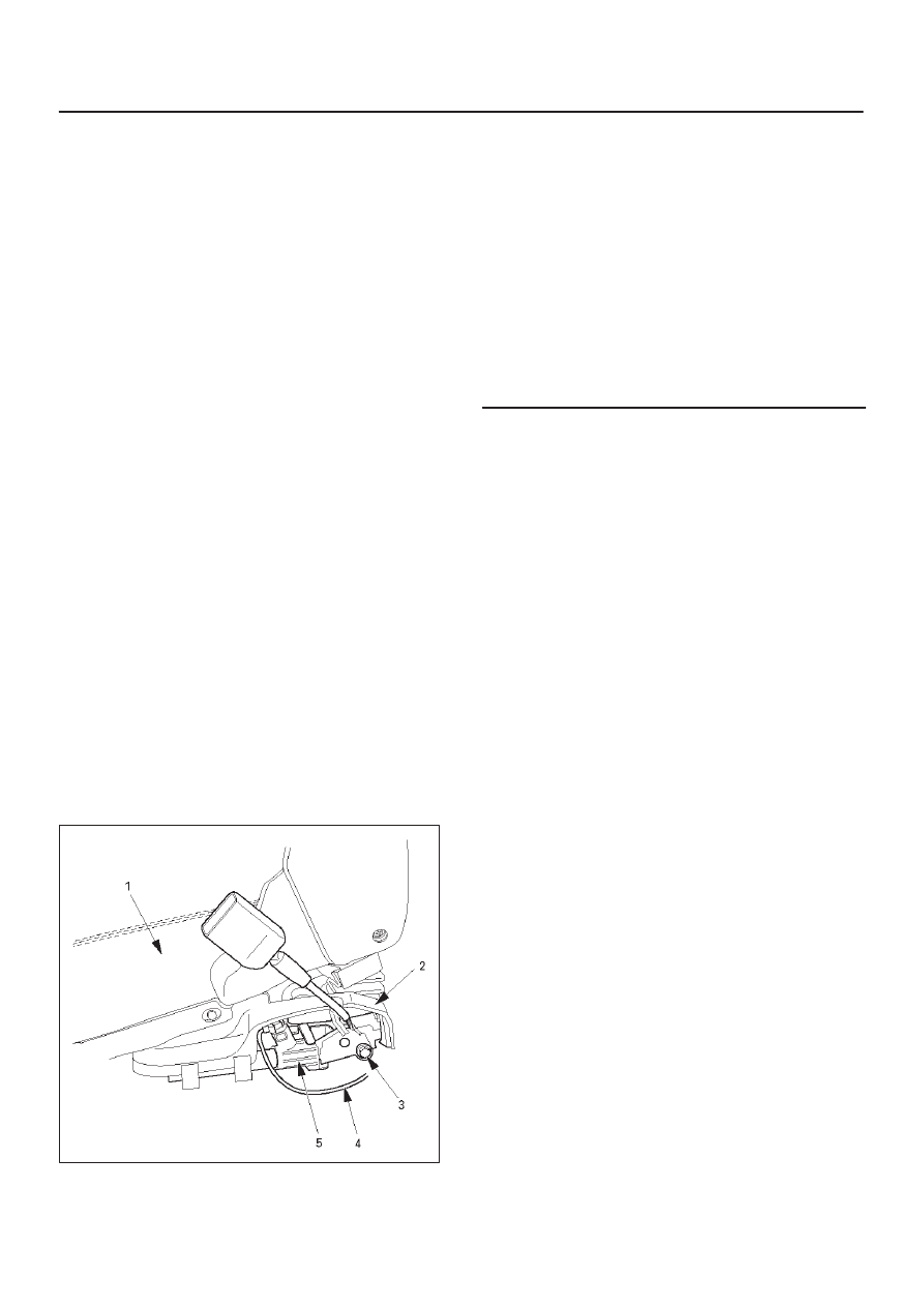
Parts Location
760RW028
Legend
(1) Seat
(2) Pretensioner Cover
(3) Bolt
(4) Pretensioner Harness
(5) Pretensioner
Removal
1. Turn ignition switch to “LOCK”, remove key.
2. Remove the foot rest located behind the seat.
3. Remove the cover on seat slide.
4. Disconnect the 2-pin connector at the base of the
seat.
5. Remove four fixing bolts the seat slide and remove
seat.
6. Remove the pretensioner seat belt cover.
7. Remove the pretensioner seat belt assembly.
Installation
1. Install the pretensioner seat belt assembly.
2. Install the pretensioner seat belt cover.
3. Install the seat on seat slide and four fixing bolts.
4. Connect the yellow 2-pin connector at the base of the
seat.
5. Install the cover on seat slide.
6. Install the foot rest located behind the seat.
Нет комментариевНе стесняйтесь поделиться с нами вашим ценным мнением.
Текст