Opel Frontera UBS. Service manual — part 2131
6E–97
ENGINE DRIVEABILITY AND EMISSIONS
Exhaust Gas Recirculation (EGR) System Check
D06RW106
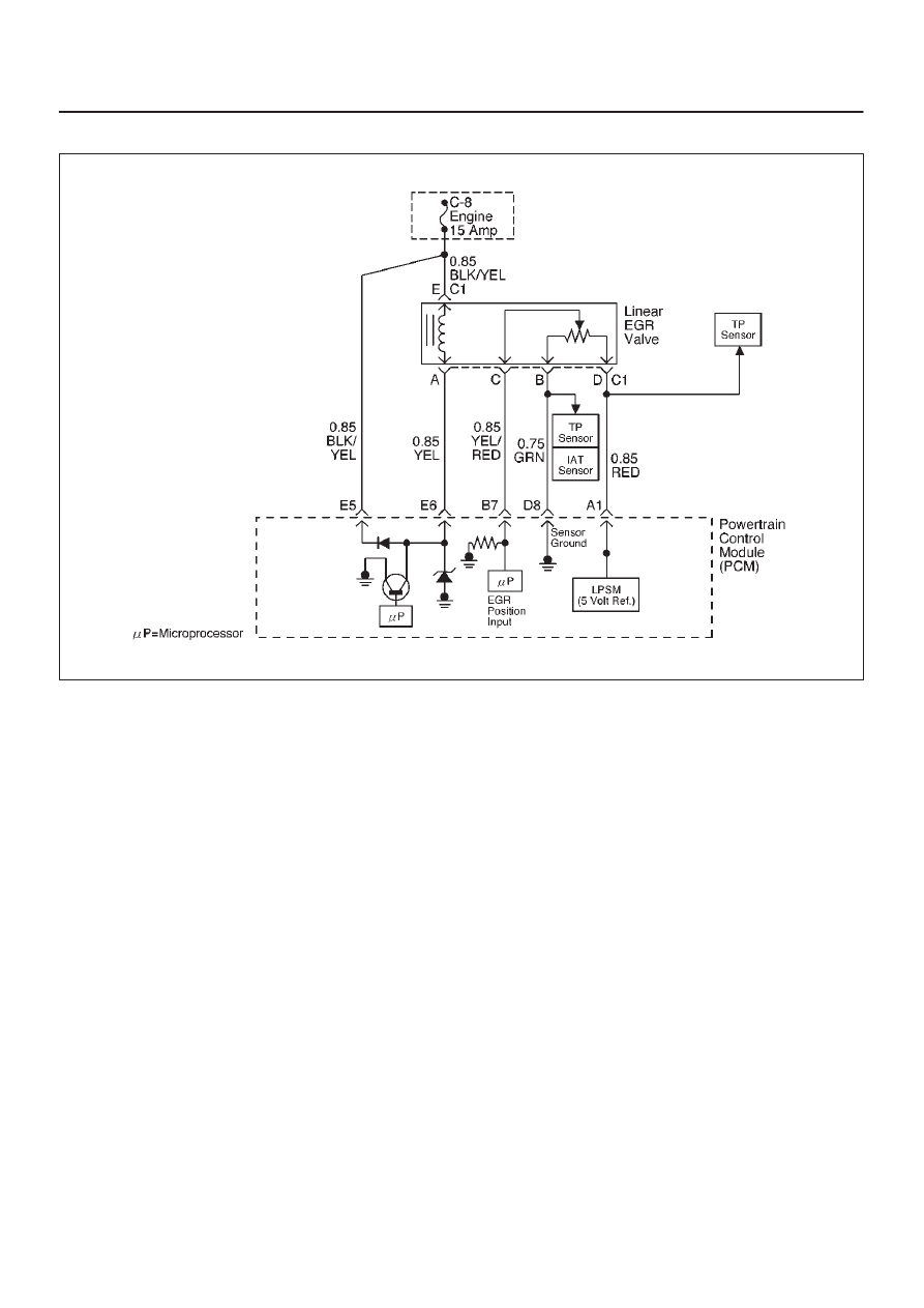
Circuit Description
A properly operation exhaust gas recirculation (EGR)
system will directly affect the air/fuel requirements of the
engine. Since the exhaust gas introduced into the air/fuel
mixture is an inert gas (contains very little or no oxygen),
less fuel is required to maintain a correct air/fuel ratio.
Introducing exhaust gas into the combustion chamber
lowers combustion temperatures and reduces the
formation of oxides of nitrogen (NOx) in the exhaust gas.
Lower combustion temperatures also prevent detonation.
If the EGR pintle were to stay closed, the inert exhaust
gas would be replaced with air and the air/fuel mixture
would be leaner. The powertrain control module (PCM)
would compensate for the lean condition by adding fuel,
resulting in higher long term fuel trim values.
Diagnostic Aids
The EGR valve chart is a check of the EGR system. An
EGR pintle constantly in the closed position could cause
detonation and high emissions of NOx. It could also result
in high long term fuel trim values in the open throttle cell,
but not in the closed throttle cell. An EGR pintle
constantly in the open position would cause a rough idle.
Also, an EGR mounted incorrectly (rotated 180
°
) could
cause rough idle. Check for the following items:
D
EGR passages – Check for restricted or blocked EGR
passages.
D
Manifold absolute pressure sensor – A manifold
absolute pressure sensor may shift in calibration
enough to affect fuel delivery. Refer to
Manifold
Absolute Pressure Output Check.

6E–98
ENGINE DRIVEABILITY AND EMISSIONS
Exhaust Gas Recirculation (EGR) System Check
Step
Action
Value(s)
Yes
No
1
Check the EGR valve for looseness.
Is the EGR valve Loose?
—
Go to
Step 2
Go to
Step 3
2
Tighten the EGR valve.
Is the action complete?
—
Verify repair
—
3
1. Place the transmission selector in Park or Neutral.
2. Start the engine and idle until warm.
3. Using Tech 2, command EGR “50% ON.”
Does the engine idle rough and lose RPMs?
—
EGR system
working
properly. No
problem
found.
Go to
Step 4
4
1. Engine “OFF.”
2. Ignition “ON.”
3. Using a test light to ground, check the EGR harness
between the EGR valve and the ignition feed.
Does the test light illuminate?
—
Go to
Step 6
Go to
Step 5
5
Repair the EGR harness ignition feed.
Was the problem corrected?
—
Verify repair
Go to
Step 6
6
1. Remove the EGR valve.
2. Visually and physically inspect the EGR valve
pintle, valve passages and adapter for excessive
deposits, obstructions or any restrictions.
Does the EGR valve have excessive deposits,
obstructions or any restrictions?
—
Go to
Step 7
Go to
Step 8
7
Clean or replace EGR system components as
necessary.
Was the problem corrected?
—
Verify repair
Go to
Step 8
8
1. Ground the EGR valve metal case to battery (–).
2. Using Tech 2, command EGR “ON” and observe the
EGR valve pintle for movement.
Does the EGR valve pintle move according to
command?
—
Go to
Step 9
Go to
DTC
P1406 chart
9
1. Remove the EGR inlet and outlet pipes from the
intake and exhaust manifolds.
2. Visually and physically inspect manifold EGR ports
and EGR inlet and outlet pipes for blockage or
restriction caused by excessive deposits or other
damage.
Do the manifold EGR ports or inlet and outlet pipes
have excessive deposits, obstructions, or any
restrictions?
—
Go to
Step 10
EGR system
working
properly. No
problem
found.
10
Clean or replace EGR system components as
necessary.
Is the action complete?
—
Verify repair
—
6E–99
ENGINE DRIVEABILITY AND EMISSIONS
Manifold Absolute Pressure (MAP) Output Check
D06RW102
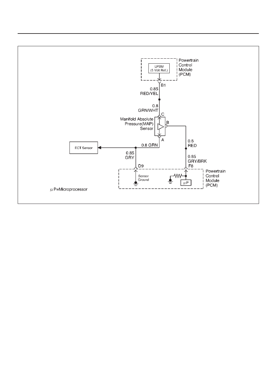
Circuit Description
The manifold absolute pressure (MAP) sensor measures
the changes in the intake MAP which result from engine
load (intake manifold vacuum) and engine speed
changes; and converts these into a voltage output. The
powertrain control module (PCM) sends a 5-volt
reference voltage to the MAP sensor. As the MAP
changes, the output voltage of the sensor also changes.
By monitoring the the sensor output voltage, the PCM
knows the MAP. A lower pressure (low voltage) output
voltage will be about 1-2 volts at idle. Higher pressure
(high voltage) output voltage will be about 4-4.8 volts at
wide open throttle. The MAP sensor is also used, under
certain conditions, to measure barometric pressure,
allowing the PCM to make adjustments for different
altitudes. The PCM uses the MAP sensor to diagnose
proper operation of the EGR system, in addition to other
functions.
Test Description
IMPORTANT:
Be sure to used the same diagnostic test
equipment for all measurements.
The number(s) below refer to the step number(s) on the
Diagnostic Chart.
2. Applying 34 kPa (10 Hg) vacuum to the MAP sensor
should cause the voltage to be 1.5-2.1 volts less
than the voltage at step 1. Upon applying vacuum
to the sensor, the change in voltage should be
instantaneous. A slow voltage change indicates a
faulty sensor.
3. Check the vacuum hose to the sensor for leaking or
restriction, Be sure that no other vacuum devices
are connected to the MAP hose.
IMPORTANT:
Make sure the electrical connector
remains securely fastened.
4. Disconnect the sensor from the bracket. Twist the
sensor with your hand to check for an intermittent
connection. Output changes greater than 0.10 volt
indicate a bad sensor.

6E–100
ENGINE DRIVEABILITY AND EMISSIONS
Manifold Absolute Pressure (MAP) Output Check
Step
Action
Value(s)
Yes
No
1
1. Turn the ignition “OFF”and leave it “OFF” for 15
seconds.
2. Ignition “ON.” Don’t crank engine.
3. Tech 2 should indicate a manifold absolute pressure
(MAP) sensor voltage.
4. Compare this scan reading to scan reading of a
known good vehicle obtained using the exact same
procedure as in Steps 1-4.
Is the voltage reading the same +/–0.40 volt?
—
Go to
Step 2
Go to
Step 5
2
1. Disconnect the vacuum hose at the MAP sensor
and plug the hose.
2. Connect a hand vacuum pump to the MAP sensor.
3. Start the engine.
4. Apply 34 kPa (10 Hg) of vacuum and note the
voltage change.
Is the voltage change 1.5-2.1 volts less than Step 1?
—
Go to
Step 3
Go to
Step 4
3
No trouble found. Check the sensor cover for leakage
or restriction.
Does the hose supply vacuum to the MAP sensor only?
—
Go to
Step 5
Go to
Step 4
4
Repair the material to block.
Is the action complete?
—
Verify repair
—
5
Check the sensor connection.
Is the sensor connection good?
—
Go to
Step 6
Go to
Step 7
6
Replace the sensor. Refer to
On-Vehicle Service, MAP
Sensor.
Is the action complete?
—
Verify repair
—
7
Repair the poor connection.
Is the action complete?
—
Verify repair
—
Нет комментариевНе стесняйтесь поделиться с нами вашим ценным мнением.
Текст