Opel Frontera UBS. Service manual — part 2752
8D–208
WIRING SYSTEM
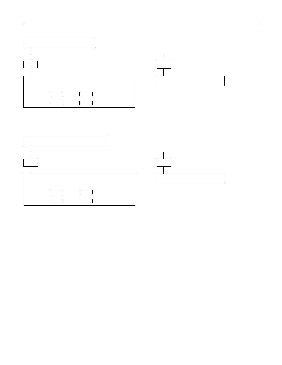
5 Turn Signal Lights On The Right (Or Left) Side Inoperative
6 Hazard Warning Lights On The Right (Or Left) Side Inoperative
•
IS TURN SIGNAL SWITCH NORMAL?
YES
NO
REPLACE OR REPAIR THE SWITCH
REPAIR A POOR CONNECTION AT THE CONNECTORS OR
AN OPEN CIRCUIT
[LH]
BETWEEN 4 B-12 AND 21 H-32
[RH]
BETWEEN 5 B-12 AND 22 H-32
•
IS HAZARD WARNING SWITCH NORMAL?
YES
NO
REPLACE OR REPAIR THE SWITCH
REPAIR A POOR CONNECTION AT THE CONNECTORS OR
AN OPEN CIRCUIT
[LH]
BETWEEN 6 I-11 AND 21 H-32
[RH]
BETWEEN 4 I-11 AND 22 H-32

WIRING SYSTEM
8D–209
7 Turn Signal Lights and Hazard Warning Lights On The Right (Or Left) Side Inoperative
REPAIR A POOR CONNECTION AT THE CONNECTORS OR
AN OPEN CIRCUIT
[LH]
BETWEEN 4 B-12 AND 21 H-32
[RH]
BETWEEN 5 B-12 AND 22 H-32
8D–210
WIRING SYSTEM
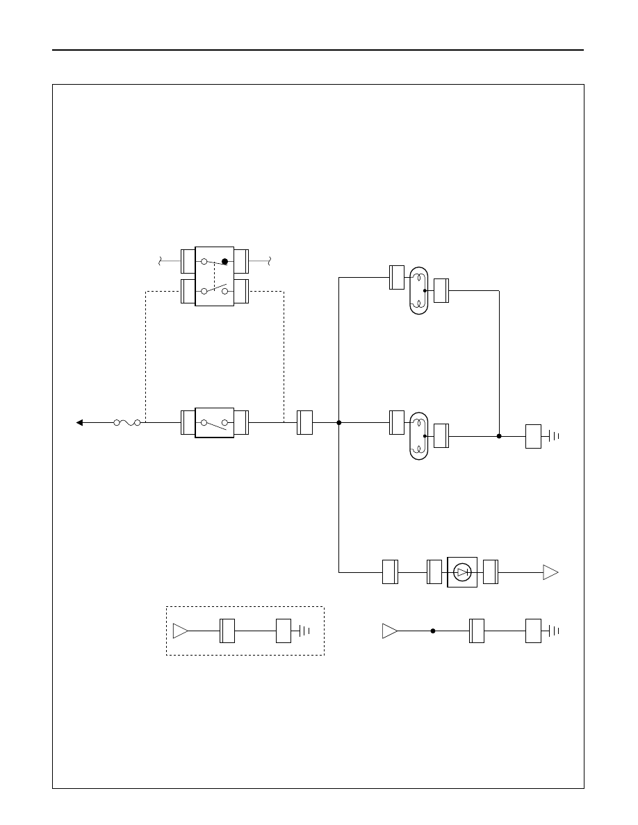
Stoplight
General Description
The circuit consists of the stoplight, stoplight switch
(vehicles w/o cruise control), brake switch (vehicles
w/ cruise control).
With the brake pedal depressed, the stoplight switch
or the brake switch is turned on to illuminate the
stoplight. The brake switch controls not only the
operation of the stoplight but also the input of the
cruise cancel signals to the cruise control unit.
WIRING SYSTEM
8D–211
5.0
W
0.85
G/W
0.85
G/W
(W/CRUISE CONTROL)
0.85
G/Y
0.85
G/Y
0.85
G/Y
0.85
G/Y
0.85
G/Y
0.85
G/Y
3.0
B
0.5
B
3.0
B
0.5
B
1.25
B
1.25
B
BA
TT
.(+)
ST
OPLIGHT
SW
ST
OPLIGHT
-LH(BODY)
HIGH MOUNTED
ST
OPLIGHT
BRAKE SW
C-14 15A
ST
OP
,A/T
CONT
B-14
2
1
B-13
1
B-13
2
A
B-14
4
B-13
3
B-13
H-32
7
R-13
5
R-13
1
0.85
G/Y
ST
OPLIGHT
-RH(BODY)
R-12
5
R-12
1
R-4
A
R-3
BODY
-RR
BODY
-RR
H-37
4
H-37
1
G-9
G-9
2
1
A
H-37
BODY
-RR
(W/O RR WIPER
AND/OR RR DEFOGGER)
0.5
B
3.0
B
4
R-3
D08RW989
Circuit Diagram (RHD)
Нет комментариевНе стесняйтесь поделиться с нами вашим ценным мнением.
Текст