Opel Frontera UBS. Service manual — part 182
4D1–30 TRANSFER CASE (STANDARD TYPE)
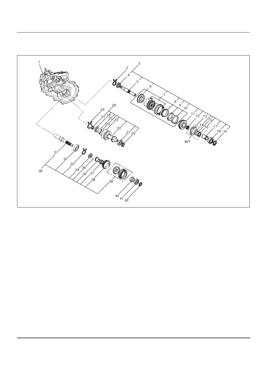
Transfer Case Assembly
Disassembled View
226RW132
Legend
(1) Transfer Case (with oil seal)
(2) Bearing Snap Ring
(3) Front Output Gear Assembly
(4) Ball Bearing
(5) Front Output Shaft
(6) Stopper Plate (Shift On The Fly model)
(7) 2WD–4WD Clutch Hub and Sleeve Assembly
(8) Block Ring (Shift On The Fly model)
(9) Outside Ring (Shift On The Fly model)
(10) Inside Ring (Shift On The Fly model)
(11) Front Output Gear
(12) Needle Bearing
(13) Sub–Gear (anti–lash plate) (M/T)
(14) Belleville Spring (M/T)
(15) Spacer (M/T)
(16) Sub–Gear Snap Ring (M/T)
(17) Bearing Collar
(18) Ball Bearing
(19) Bearing Snap Ring
(20) Snap Ring
(21) Ball Bearing
(22) Counter Gear
(23) Sub–Gear (anti–lash plate)
(24) Belleville Spring
(25) Spacer
(26) Ball Bearing
(27) Snap Ring
(28) Counter Gear Assembly
(29) Bearing Snap Ring
(30) Input Shaft Assembly
(31) Input Shaft
(32) Ball Bearing
(33) Snap Ring
(34) Plate
(35) Ball
(36) Bearing Collar
(37) Needle Bearing
(38) Transfer Input Gear
(39) High–Low Clutch Hub and Sleeve Assembly
(40) Lock Nut
(41) Ball Bearing
(42) Bearing Snap Ring
TRANSFER CASE (STANDARD TYPE)
4D1–31
Disassembly
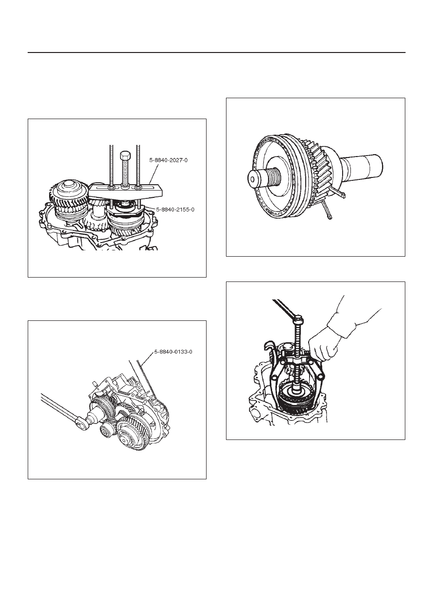
1. Use a pair of snap ring pliers to remove the snap ring
(42).
2. Use a bearing remover 5–8840–2155–0 ( J–37217)
and puller 5–8840–2027–0 (J–37487) to remove the
ball bearing (41).
262RW069
3. Install the front companion flange temporarily.
4. Use the Companion flange holder 5–8840–0133–0
(J–8614–11) and lock nut wrench 5–8840–2156–0
(J–37219) to remove the lock nut (40).
226RW189
5. Remove the front companion flange.
6. Remove the snap ring (33) from the transfer case (1).
7. Remove the input shaft assembly (30) from the
transfer case.
265RW001
8. Use a universal puller to remove the high–low clutch
hub and sleeve (39), and transfer input gear (38).
226RS070
9. Remove needle bearing (37).
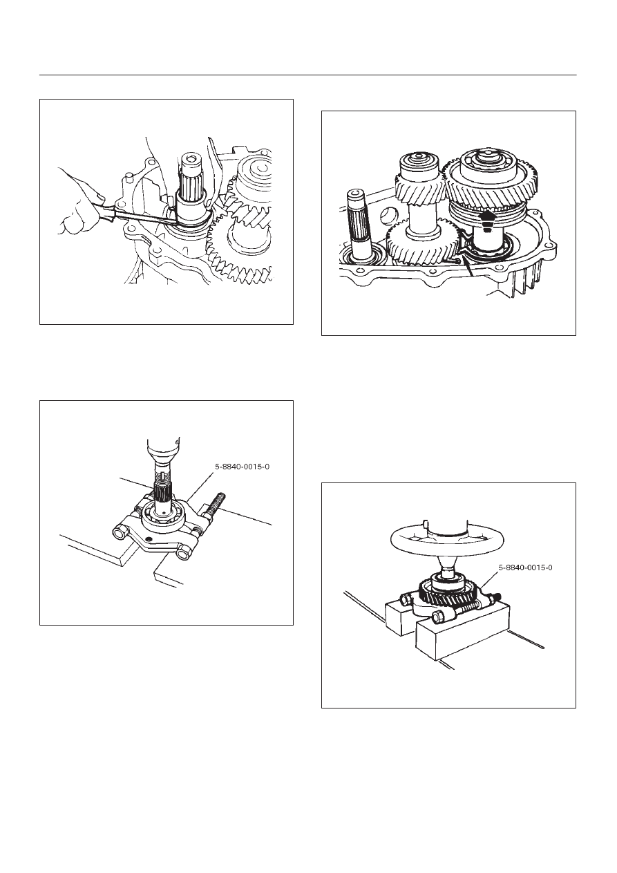
4D1–32 TRANSFER CASE (STANDARD TYPE)
10. Remove the bearing collar (36).
226RS071
11. Remove the ball (35).
12. Remove the plate (34).
13. Use a bench press and the ball bearing remover
5–8840–0015–0 (J–22912–01) to remove the ball
bearing (32) from input shaft (31).
265RW013
14. Remove the bearing snap ring (2) from the transfer
case, using a pair of snap ring pliers.
15. Use a plastic hammer to tap the front output gear
assembly (3) free.
262RS009
16. Remove the bearing snap ring (19). Remove the ball
bearing (18) and bearing collar (17) together with
front output gear assembly: including following parts.
17. Use a bench press and the bearing remover
5–8840–0015–0 (J–22912–01) to remove the
following parts.
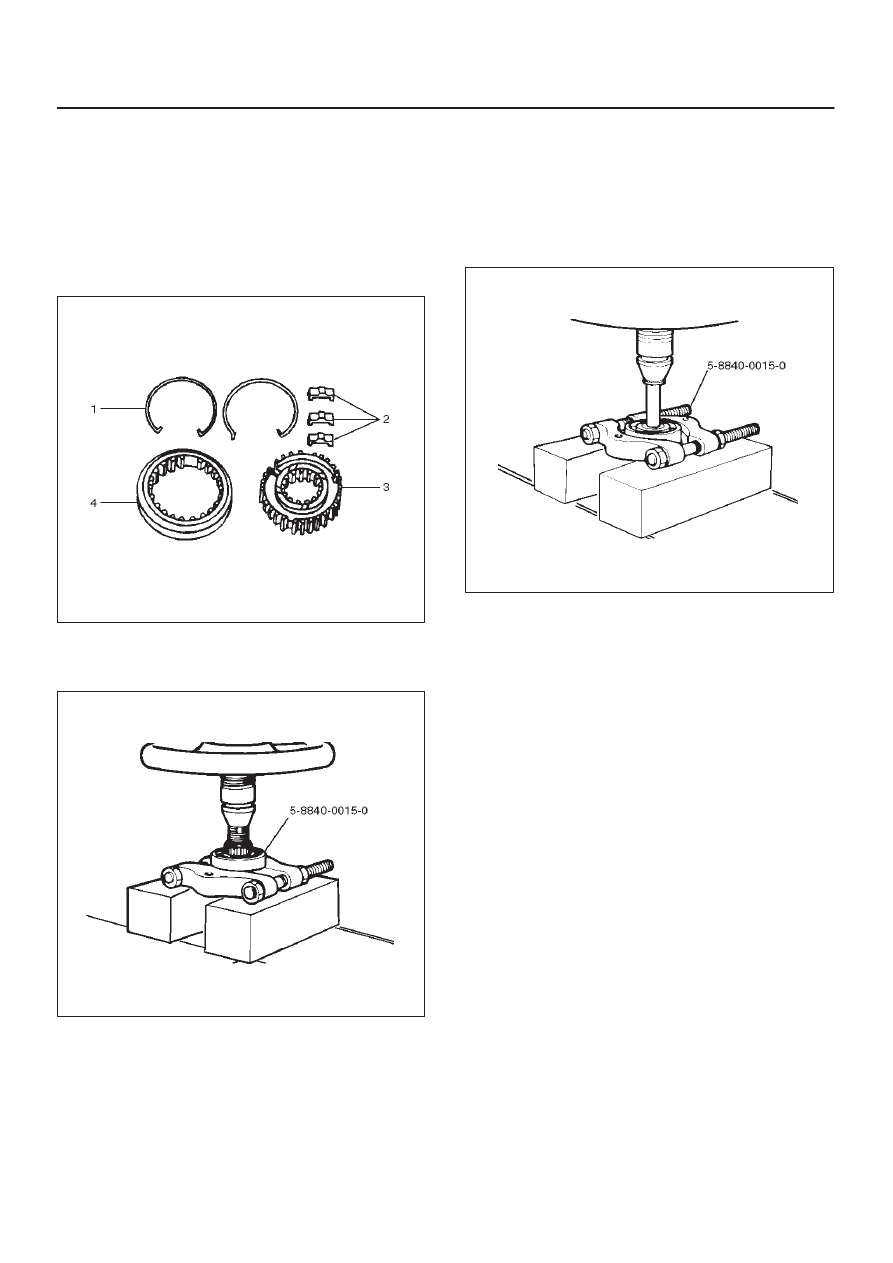
18. Remove the sub–gear snap ring (16), spacer (15),
belleville spring (14), and sub–gear (anti–lash plate)
(13).(M/T)
19. Remove the front output gear (11) and needle bearing
(12).
262RW070
20. Remove the inside ring (10). (Shift On The Fly model)
21. Remove the outside ring (9). (Shift On The Fly model)
22. Remove the block ring (8). (Shift On The Fly model)
23. Use a bench press and bearing remover
5–8840–0015–0 (J–22912–01) to remove the
2WD–4WD clutch hub and sleeve assembly (7) and
stopper plate (6). (Shift On The Fly model)
TRANSFER CASE (STANDARD TYPE)
4D1–33
NOTE: Do not reuse the stopper plate. (Shift On The Fly
model)
24. Disassemble the 2WD–4WD clutch hub and sleeve
assembly.
D
Springs (1) (Shift On The Fly model)
D
Inserts (2) (Shift On The Fly model)
D
Clutch Hub (3)
D
Sleeve (4)
226RW133
25. Use a bench press and the ball bearing remover
5–8840–0015–0 (J–22912–01) to remove the ball
bearing (4) from front output shaft (5).
262RW071
26. Remove bearing snap ring (29) from transfer case.
27. Remove the counter gear assembly (28) from the
transfer case (1).
28. Use a pair of snap ring pliers to remove the snap ring
(20).
29. Use a bench press and the bearing remover
5–8840–0015–0 (J–22912–01) to remove the ball
bearing (21).
30. Use a pair of snap ring pliers to remove the snap ring
(27).
31. Use a bench press and the bearing remover
5–8840–0015–0 (J–22912–01) to remove the ball
bearing (26).
226RW191
32. Remove the spacer (25).
33. Remove the belleville spring (24).
34. Remove the sub–gear (anti–lash plate) (23) from the
counter gear (22).
Inspection and Repair
1. Make the necessary repair or parts replacement if
wear, damage or any other abnormal conditions are
found during inspection.
2. Wash all parts thoroughly in clean solvent. Be sure all
old lubricant, metallic particles, dirt, or foreign
material are removed from the surfaces of every part.
Apply compressed air to each oil feed port and
channel in each case half to remove any obstructions
or cleaning solvent residue.
Gears
1. Inspect all the gear teeth for signs of excessive wear
or damage and check all the gear splines for burrs,
nicks, wear or damage. Remove the minor nicks or
scratches on an oil stone. Replace any part exhibiting
excessive wear or damage.
Front Output Gear Inside Diameter
1. Use an inside dial indicator to measure the gear inside
diameter.
Нет комментариевНе стесняйтесь поделиться с нами вашим ценным мнением.
Текст