Opel Frontera UBS. Service manual — part 2522
7A–46
AUTOMATIC TRANSMISSION (4L30–E)
Transmission (4L30–E)
Disassembly
NOTE: During the disassembly and reassembly, perform
the following:
D
Wash each part thoroughly, and blow air through each
oil passage and groove to eliminate blockage.
D
Seal rings, roll pins, and gaskets should be replaced.
D
When assembling the components, apply
DEXRON
–III Automatic Transmission Fluid (ATF)
to each seal, rotating part, and sliding part.
D
Do not dip part facings, such as clutch or brake drive
plates, in cleaner when washing it.
Also, always coat parts with new ATF two or three
times after cleaning with solvent.
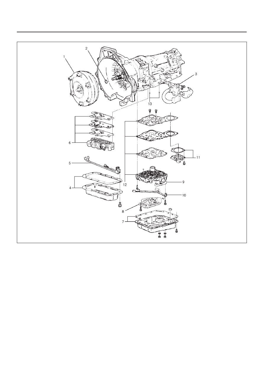
1. Remove torque converter (1).
D
Drain fluid from torque converter.
D
Attach 5–8840–2278–0 (J–8763–02) holding
fixture to the transmission and set it on
5–8840–0003–0 (J–3289–20) holding fixture base.
NOTE: Do not overtighten the tool, as case damage may
result.
420RW019
2. Remove O–ring (2) from turbine shaft.
3. Remove two 10mm mode switch screws, selector
lever nut, cover, and mode switch (3).
4. Remove twelve 10mm adapter case oil pan (4) fixing
screws, adapter oil pan, and gasket.
5. Disconnect electrical wiring connections (5) from
solenoids and 4 way connector of adapter case. Pull
on connectors only, not on wiring harness.
6. Remove seven 13mm adapter case valve body (6)
fixing screws, adapter case valve body assembly,
transfer plate, and two gaskets.
D
Remove wiring harness and 4 way connector.
7. Remove sixteen 10mm main case oil pan (7) fixing
screws, main oil pan, magnet, and gasket.
8. Remove three 13mm oil filter (8) fixing screws and oil
filter.
9. Remove two 13mm manual detent (9) fixing screws,
roller and spring, and manual detent.
10. Disconnect wiring harness assembly (10) from band
apply solenoid, shift solenoids, and main case 7 way
connector.
Pull on connectors only, not on wiring harness.
11. Remove four 13mm servo cover (11) fixing screws,
servo cover, and gasket.
12. Remove seven 13mm valve body screws and ground
wire from main case.
D
Remove wiring harness assembly (5) from the
adapter case side.
D
Remove main valve body assembly (12) with
manual valve link and transfer plate. Note the
position of the link (long end into valve, short end
into range selector lever).
D
Remove 7 way connector.
D
Remove gasket transfer plate from main case.
7A–47
AUTOMATIC TRANSMISSION (4L30–E)
13. Remove two check balls (13) from main case.
240RY001
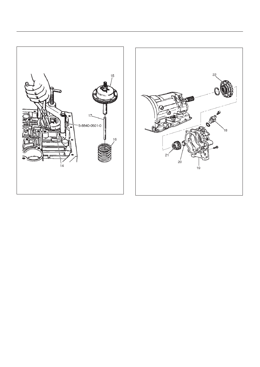
14. Turn transmission to vertical position to drain fluid.
Return back to horizontal position when drained.
D
Install 5–8840–0501–0 (J–23075) servo piston
spring compressor with offset to the rear of case.
D
Compress servo piston assembly.
D
Remove servo piston retaining ring (14).
D
Slowly release servo piston assembly (15).
D
Remove tool.
7A–48
AUTOMATIC TRANSMISSION (4L30–E)
15. Remove servo piston assembly (15), return spring
(16), and servo apply rod (17).
242RW006
16. Rotate transmission to horizontal position, pan side
down.
D
Remove one 10mm screw, and speed sensor (18)
with “O” ring.
17. Remove seven 8mm extension housing hexagon
socket head screws, extension housing assembly
(19), and gasket.
18. Remove retaining ring (20).
NOTE: Use extra long, needle- nose pliers.
19. Remove speed wheel (21).
20. Remove wheel parking lock (with seal ring) (22).
241RS002
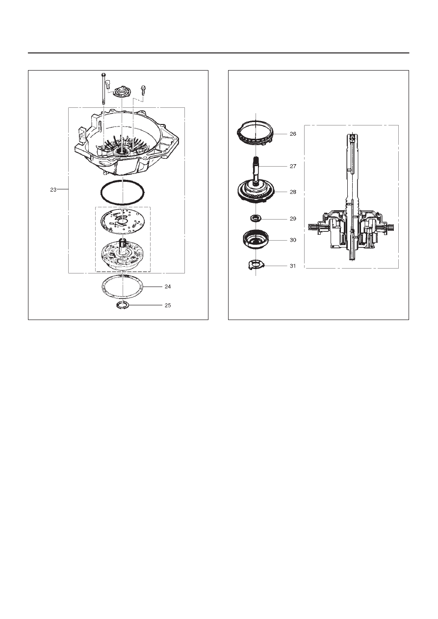
21. Rotate transmission to vertical position, converter
housing up.
D
Loosen the converter housing and oil pump
assembly fixing screws, but do not remove the five
13 mm inner screws if oil pump disassembly is
required.
D
Remove seven outer screws.
D
Remove converter housing and oil pump assembly
(23).
22. Remove gasket (24).
7A–49
AUTOMATIC TRANSMISSION (4L30–E)
23. Remove selective thrust washer (25).
241RW004
24. Remove fourth clutch retainer (26).
25. Grasp turbine shaft and lift out the overrun clutch
housing assembly (27) and fourth clutch plates (28).
26. Remove thrust bearing assembly (29).
27. Remove overdrive internal gear (30).
28. Remove thrust washer (31).
252RS001
29. Remove adapter case and center support assembly
(with fourth clutch piston) (32).
30. Remove seal ring (33).
31. Remove selective thrust washer (34) and two O–ring
seals (35) from main case.
32. Use 5–8840–0195–0 (J–23327) and 5–8840–2263–0
(J–23327–90) compressor to compress the fourth
clutch spring retainer and springs (37).
D
Release snap ring (36) from groove.
D
Remove clutch compressor and snap ring (36).
33. Remove retainer and spring assembly (37).
34. Insert two converter housing/main case screws to
hold adapter case while pulling out fourth clutch
piston (38).
D
Remove fourth clutch piston assembly (38) from the
adapter case.
D
Remove converter housing/main case screws.
35. Grasp intermediate shaft, twist and pull out the
second and third clutch drum assemblies with reverse
clutch plates while holding onto output shaft (39).
Нет комментариевНе стесняйтесь поделиться с нами вашим ценным мнением.
Текст