Opel Frontera UBS. Service manual — part 1929
DIFFERENTIAL (FRONT)
4A1–6
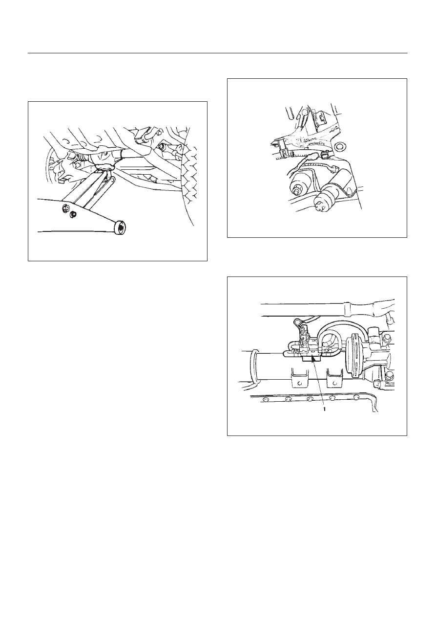
3. Remove the drain bolt to drain differential oil.
NOTE:
a. During the work, be sure that the diff case is
supported by the jack.
412RS003
b. Remove the brake caliper fixing bolt and hang the
caliper. Refer to Front Disc Brake Caliper Assembly
in Brake section.
c. Remove the antilock brake system speed sensor (if
equipped). Refer to Front Wheel Speed Sensor in
Brakes section.
4. Remove the hub assembly (Disc, back plate and
knuckle), refer to Front Hub and Disc in this section.
5. Disconnect the knuckle and the suspension arm.
Refer to Suspension section.
6. Remove steering link and arm assembly, refer to
Steering Linkage in Steering section.
7. Remove suspension crossmember.
8. Remove propeller shaft, refer to Front Propeller Shaft
in this section.
9. Remove protector (Shift on the fly model).
10. Remove the hose clip.
11. Disconnect breather hose from front drive axle tube.
(and disconnect housing : Shift on the fly model).
12. Disconnect vacuum hose from actuator (Shift on the
fly model).
13. Disconnect shift switch connector (Shift on the fly
model).
412RS031
14. Remove VSV assembly (1) (Shift on the fly model).
NOTE: Be sure not to remove hose and connector from
VSV asm.
412RW002
4A1–7
DIFFERENTIAL (FRONT)
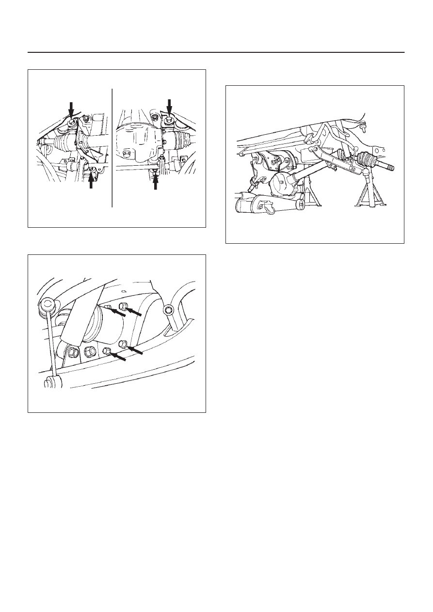
15. Remove mounting bolt and nut.
412RS004
16. Remove washer and spacer.
17. Remove the mounting bracket fixing bolt.
412RS005
18. Lower the vehicle and disconnect the RH front drive
shaft assembly, then remove the front axle case
assembly and front drive shaft assembly (LH).
412RS006
19. Remove front drive shaft assembly (RH).
Installation
1. Install front drive shaft assembly (RH) and lay the
assembly on the lower arm.
2. Install front axle case assembly and front drive shaft
assembly (LH) and place the axle case on the jack,
connect to the front drive shaft assembly (RH) before
installing to the vehicle.
3. Install bolt and tighten the mounting bracket fixing bolt
to the specified torque.
Torque: 116 N·m (11.8kg·m/85 lb ft)
4. Install washer and spacer.
DIFFERENTIAL (FRONT)
4A1–8
5. Tighten the mounting bolt and nut to the specified
torque.
Torque: 152 N·m (15.5kg·m/112 lb ft)
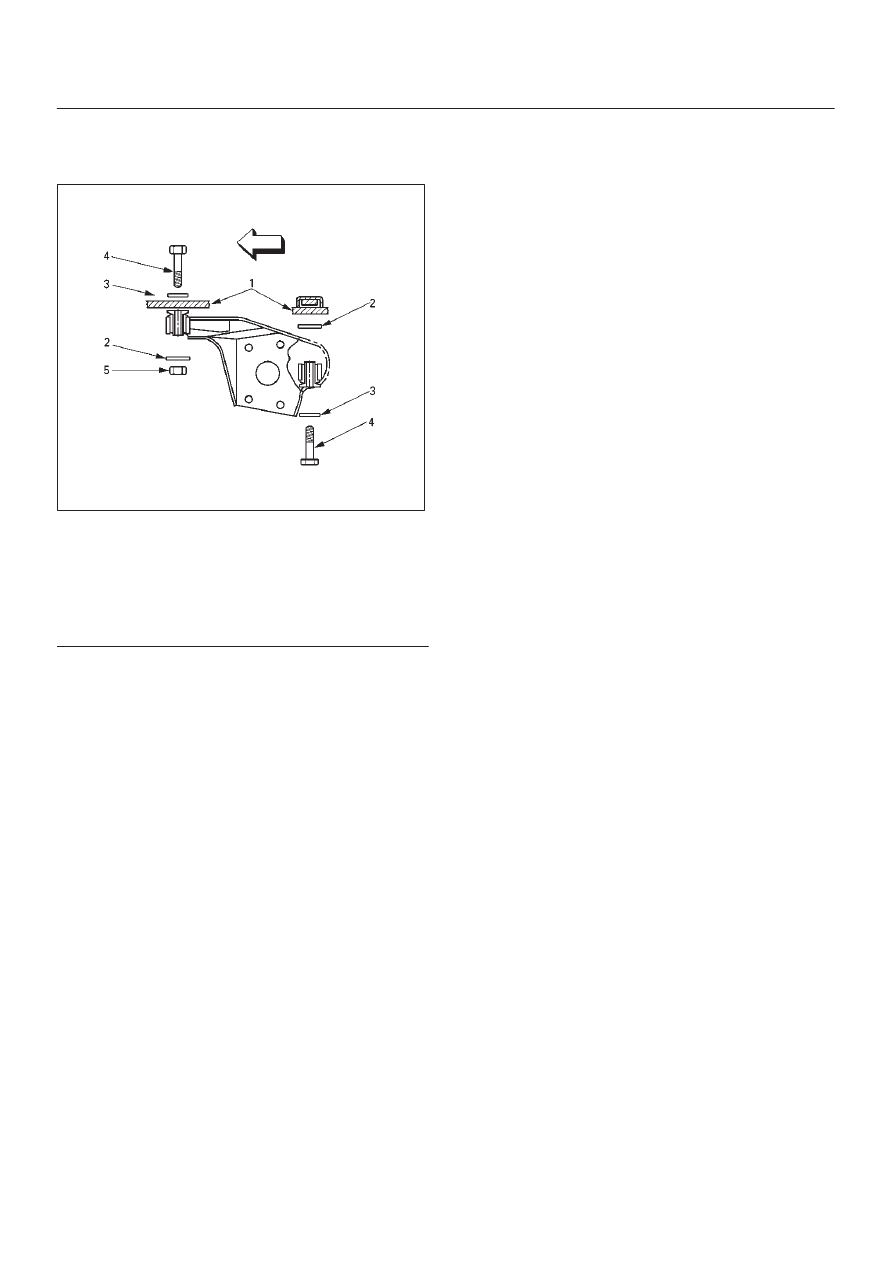
412RW005
Legend
(1) Frame
(2) Spacer
(3) Washer
(4) Bolt
(5) Nut
6. Install VSV assembly and tighten nuts to specified
torque (Shift on the fly model).
Torque: 8 N·m (0.8kg·m/69 lb in)
7. Install the shift switch connector (Shift on the fly
model).
NOTE: Be careful not to permit the entry of dust into the
connector.
8. Install the actuator side of vacuum hose (Shift on the
fly model).
NOTE: Be careful not to permit the entry of dust into the
hose.
9. Connect breather hose and install the hose clip.
10. Install protector and tighten bolts to specified torque
(Shift on the fly model).
Torque: 26 N·m (2.7kg·m/20 lb ft)
11. Install propeller shaft, refer to Front Propeller Shaft in
this section.
12. Install suspension crossmember.
13. Steering link and arm assembly, refer to Steering
Linkage in Steering section.
14. Install hub assembly (Disc, back plate and knuckle),
refer to Front Hub and Disc in this section.
4A1–9
DIFFERENTIAL (FRONT)
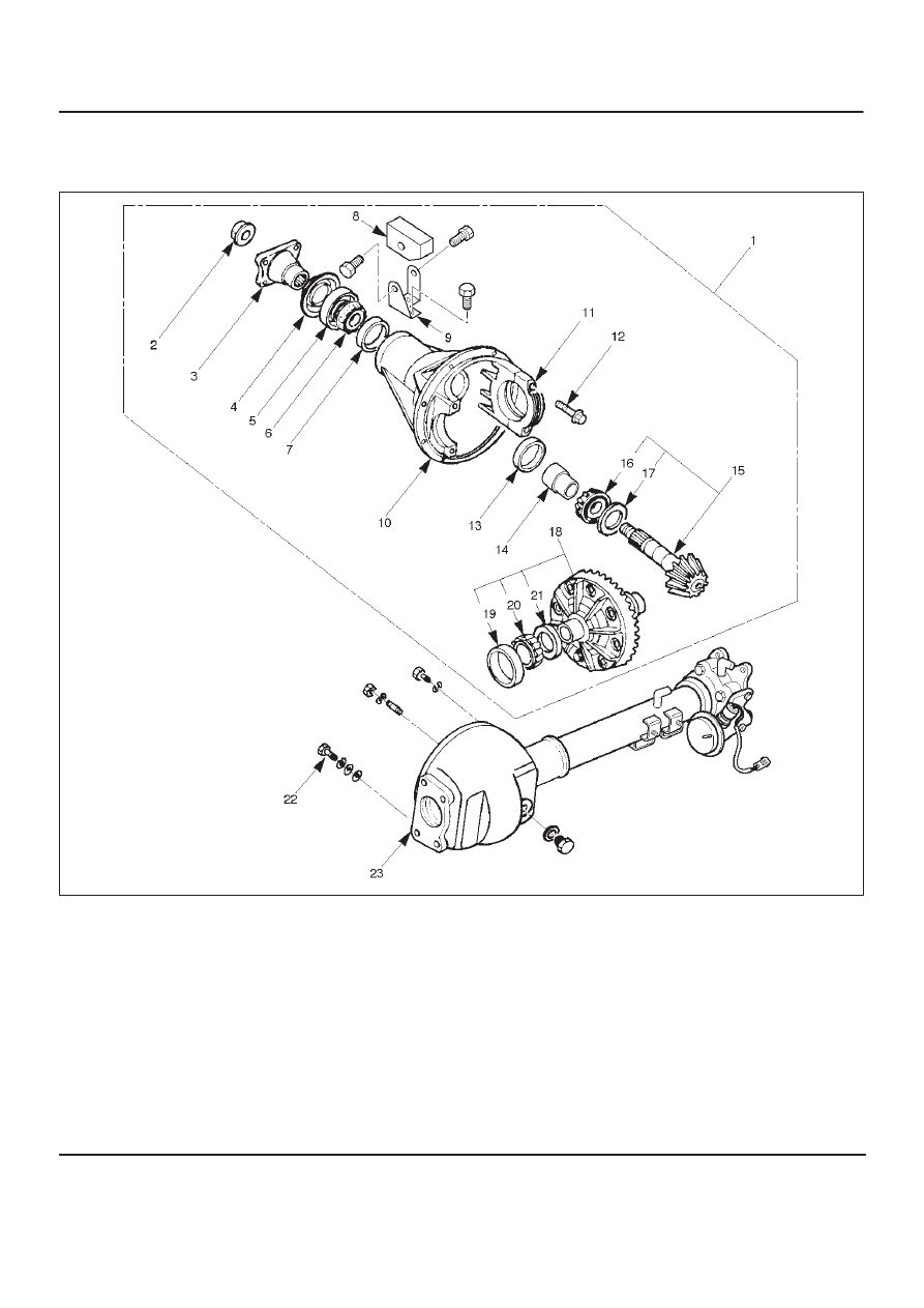
Differential Assembly
Disassembled View
415RW001
Legend
(1) Differential Assembly
(2) Flange Nut
(3) Flange
(4) Dust Cover
(5) Oil Seal
(6) Outer Bearing
(7) Outer Bearing Outer Race
(8) Damper
(9) Bracket
(10) Differential Carrier
(11) Bearing Cap
(12) Bolt
(13) Inner Bearing Outer Race
(14) Collapsible Spacer
(15) Pinion Gear
(16) Inner Bearing
(17) Adjust Shim
(18) Diff Cage Assembly
(19) Side Bearing Outer Race
(20) Side Bearing
(21) Adjust Shim
(22) Bolt
(23) Axle Case
Нет комментариевНе стесняйтесь поделиться с нами вашим ценным мнением.
Текст