Opel Frontera UBS. Service manual — part 1279
ENGINE MECHANICAL 6A – 49
14. Piston Assembly
•
Refer to “Piston and connecting rod” in this Section.
13. Tappet
12. Timing Gear Case
1) Install the timing gear case to the cylinder body.
NOTE:
Take care not to twist the front oil seal.
2) Tighten the timing gear case bolt together with the
timing gear case gasket to the specified torque.
19 (1.9/14)
N·m (kg·m/lb·ft)
3) Cut away the gasket protruding above the fitting
surfaces (as shown in the illustration).
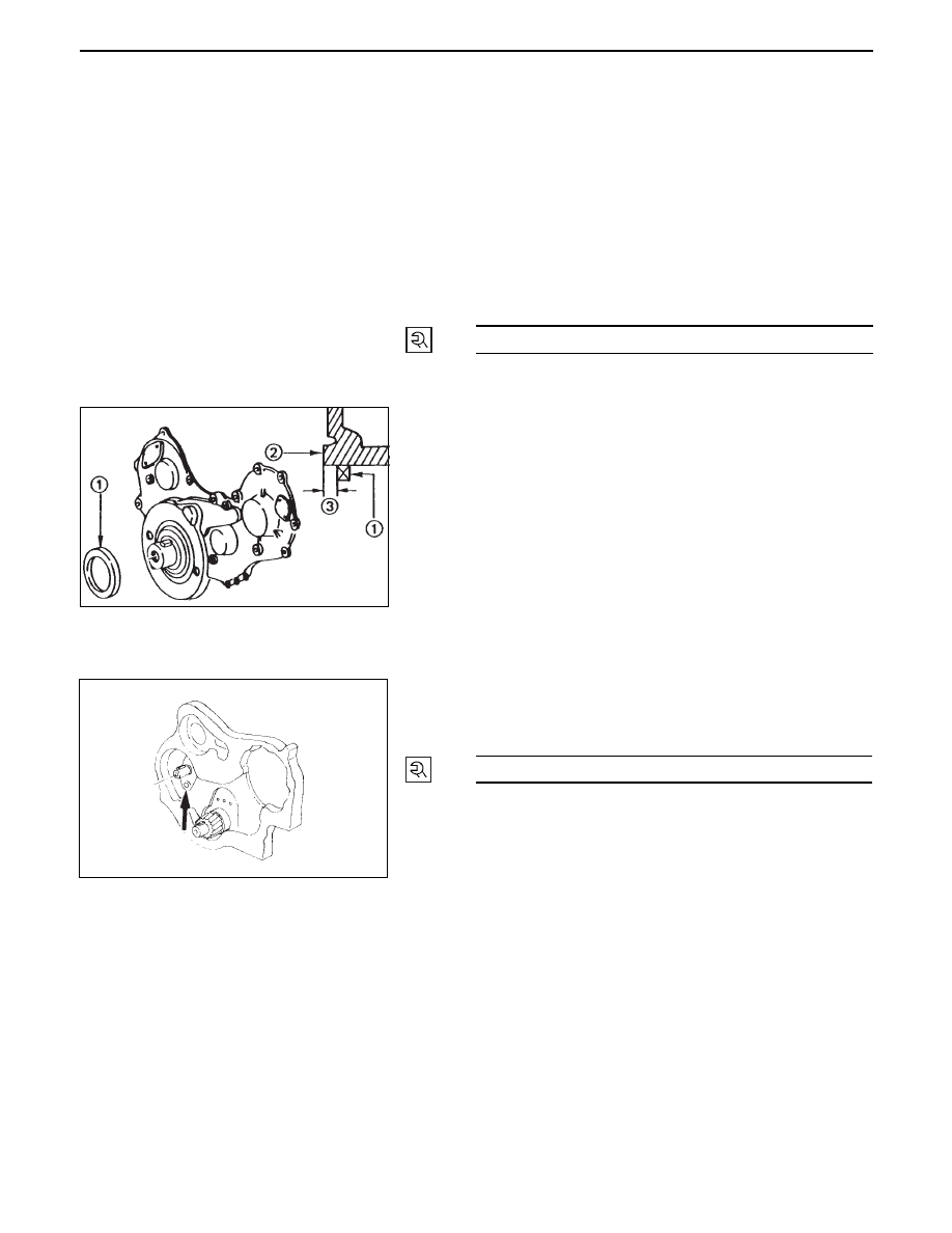
11. Crankshaft Front Oil Seal
•
Use the installer to install the front oil seal 1 to
the gear case cover 2.
Oil Seal Installer: 5-8840-2061-0
Note the oil seal installation depth 3 shown in
the illustration.
Depth 3 = 1 mm (0.039 in.)
10. Camshaft
•
Refer to ‘Camshaft, Tappet’ in Section 6A.
9.
Camshaft Thrust Plate
•
Install the thrust plate to the cylinder body and
tighten the thrust plate bolts to specified torque.
18 (1.8/13)
N·m (kg·m/lb·ft)
6A – 50 ENGINE MECHANICAL
8.
Camshaft Timing Gear
1) Install the camshaft timing gear to the camshaft.
The timing gear mark ("Y - Y") must be facing
outword.
2) Tighten the timing gear to the specified torque.
64 (6.5/47)
N·m (kg·m/lb·ft)
7.
Oil Pump Assembly
•
Refer to ‘Oil pump’ in Section 6A2.
6.
Crankcase Assembly
•
Refer to ‘Crankcase’ in Section 6A2.
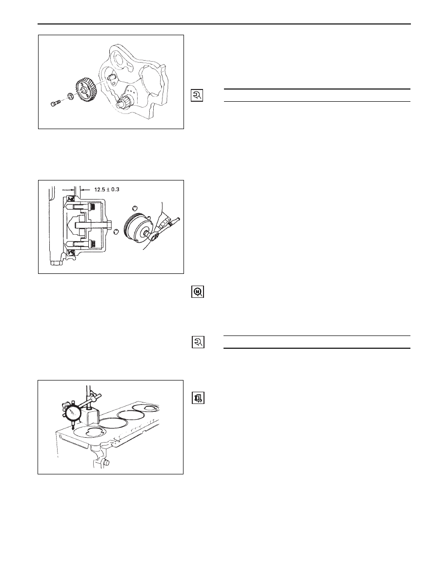
5.
Crankshaft Rear Oil Seal
1) Tighten the adapter to the crankshaft rear and
section with 2 bolts.
2) Insert the oil seal into the peripheral section of the
adapter,
3) Insert the sleeve into the adapter section, and 1)
tighten it with a bolt (M12 x 1.75L = 70) until the
adapter section hits the sleeve.
4) Remove the adapter and the sleeve.
5) With the seal pressed in, check the dimension of
the oil seal section.
Standard Dimension = 12.5 ± 0.3 mm
Oil Seal Installer:
5-8840-2359-0
4.
Cylinder Block Rear Plate
•
Tighten the cylinder block rear plate fixing bolt to the
specified torque
82 (8.4/61)
N·m (kg·m/lb·ft)
3.
Flywheel
•
Refer to ‘Crankshaft’ in Section 6A.
2.
Cylinder Head Gasket
1. Carefully remove carbon deposits and gasket
residue from the piston top face and the cylinder
body upper surface.
ENGINE MECHANICAL 6A – 51
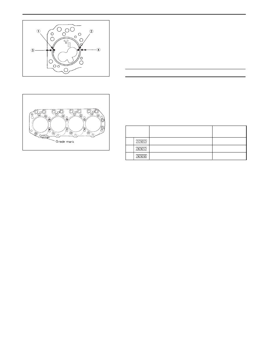
2. Use a dial indicator to measure the piston head
projection at measuring points 1 and 3 on the
piston head and measuring points 2 and 4 on
the cylinder body.
Do this for each cylinder.
3. Note the highest measured value.
This will determine the cylinder head gasket
thickness.
Piston head projection must be within the range
shown in the above table.
4. Select a cylinder head gasket of the appropriate
thickness.
The difference between the highest measured pis-
ton head projection and the lowest measured piston
head projection must not exceed mm (in).
1.
Cylinder Head Assembly
•
Refer to Section 6A2 ‘Cylinder head’
0.658 ~ 0.814 (0.0259 ~ 0.0320)
mm (in)
Piston Head Projection
Grade
mark
Average piston
projection
Gasket
thickness
(Reference)
A
0.658-0.712 (0.0259-0.0281)
1.60 (0.0630)
B
0.713-0.758 (0.0281-0.0299)
1.65 (0.0650)
C
0.759-0.813 (0.0299-0.0320)
1.70 (0.0670)
mm (in)

6A – 52 ENGINE MECHANICAL
MEMO
Нет комментариевНе стесняйтесь поделиться с нами вашим ценным мнением.
Текст