Opel Frontera UBS. Service manual — part 2010
TRANSFER CASE (STANDARD TYPE)
4D1–9
266RW002
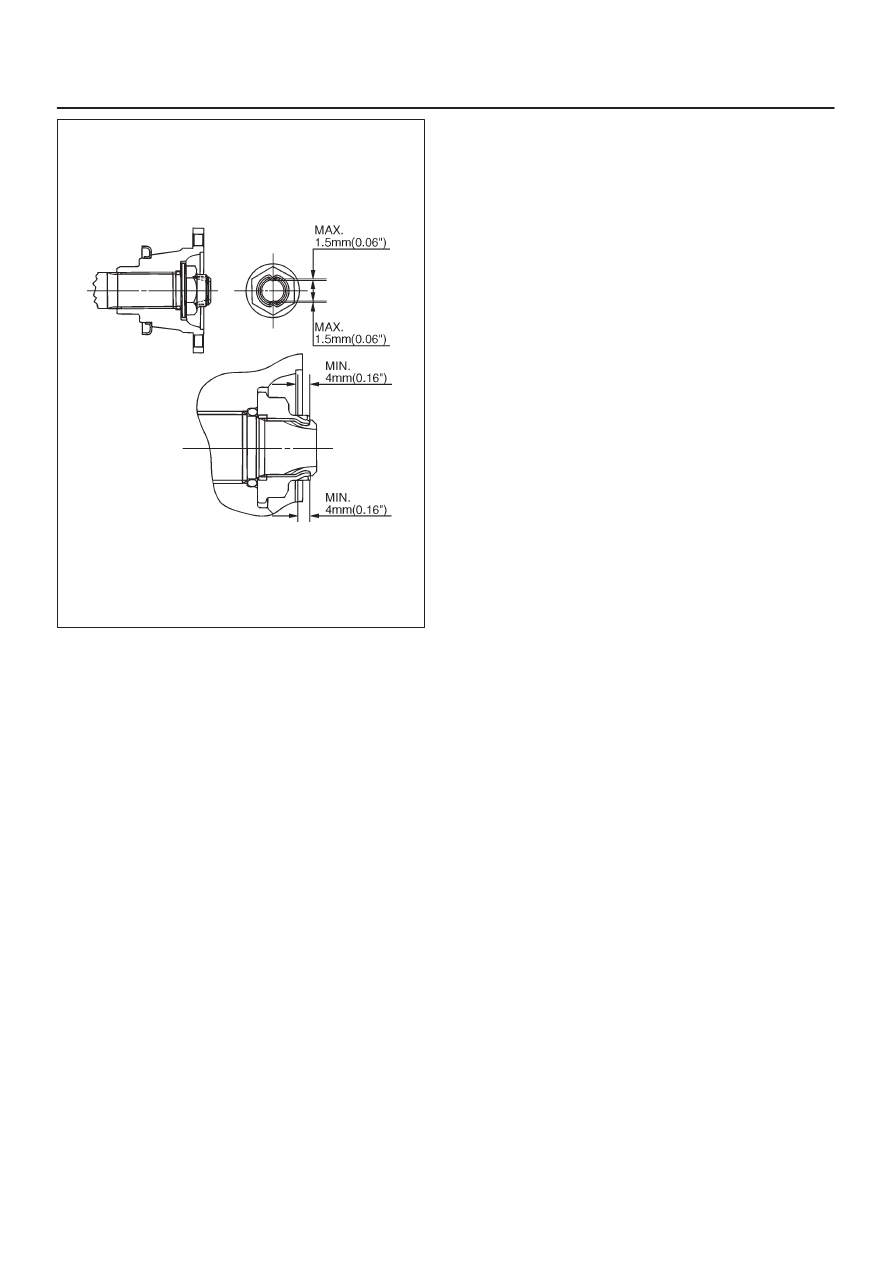
7. Connect the rear propeller shaft to the transfer case
and tighten to the specified torque.
Torque: 63 N·m (6.4kg·m/46 lb ft)
Transfer Case Assembly
Removal
NOTE: Before removing the transmission & transfer
assembly from the vehicle, change the transfer mode to
2WD by pushing button switch on dash panel. (4WD
Switch Model)
1. Disconnect the battery ground cable.
2. Drain the transfer case fluid, if overhauling the
transter case assembly.
3. Remove the exhaust and transfer protectors.
4. Remove the rear and front propeller shafts from the
transfer case side.
5. Remove the transfer control lever knob.
6. Disconnect the harness connectors and remove the
front console.
7. Remove the selector lever assembly. Refer to
Selector Lever in the Section 7A.
8. Remove the transfer control lever.
9. Disconnect the 4WD switch connector, speed sensor
harness connector and 2WD–4WD actuator harness
connector (4WD Switch Model) from the transmission
harness.
10. Support the transfer case with a transmission jack.
11. Remove the transmission–transfer bolts and the nut
(M/T).
12. Remove the transfer case assembly from the vehicle.
4D1–10 TRANSFER CASE (STANDARD TYPE)
Installation
To install, follow the removal steps in the reverse order,
noting the following points:
1. Apply a thin coat of molybdenum disulfide grease to
the input shaft spline and install the transter case
assembly to the vehicle.
260RW001
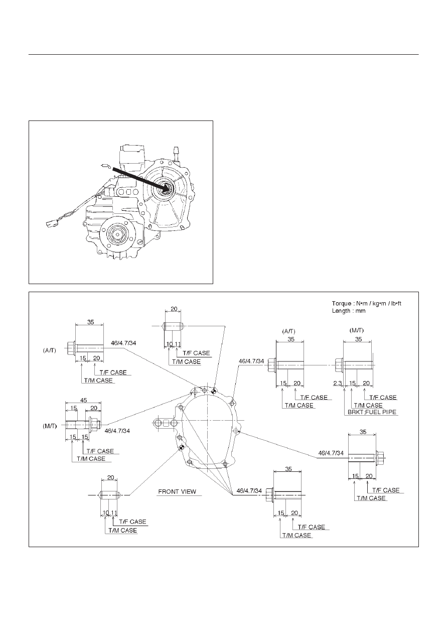
2. Tighten the transmission–transfer bolts and the nut
(M/T) to the specified torque.
Torque: 46 N·m (4.7kg·m/34 lb ft)
3. Tighten the propeller shaft bolts to the specified
torque.
Torque: 63 N·m (6.4kg·m/46 lb ft)
4. Tighten the transfer protector bolts to the specified
torque.
Torque: 37 N·m (3.8kg·m/27 lb ft)
256RW030
TRANSFER CASE (STANDARD TYPE)
4D1–11
Transfer Rear Cover Assembly (4WD Switch Model)
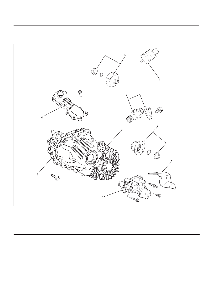
Transfer Rear Cover Assembly and Associated Parts
220RW102
Legend
(1) Speedometer Sensor, Speedometer Driven
Gear and Plate
(2) Front Companion Flange
(3) Rear Companion Flange
(4) Control Box Assembly
(5) 2WD–4WD Actuator Heat Protector
(6) 2WD–4WD Actuator Assembly
(7) Transfer Rear Cover Assembly
(8) Transfer Case Assembly
4D1–12 TRANSFER CASE (STANDARD TYPE)
Removal
1. Remove the speedometer sensor.
2. Remove the plate.
3. Remove the speedometer driven gear bushing and
driven gear.
NOTE: Apply a reference mark to the driven gear bushing
before removal.
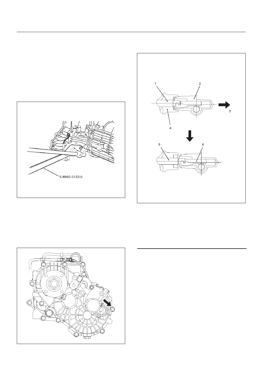
4. Remove the front companion flange and the rear
companion flange, using the flange companion holder
5–8840–0133–0 (J–8614–11) to remove the end
nuts.
262RW067
NOTE: Use a universal puller to remove the rear
companion flange.
5. Disconnect the actuator breather hose and the
transfer breather hose from the control box.
6. Remove the control box assembly.
7. Disconnect the actuator breather hose and remove
the 2WD–4WD actuator heat protector from the
2WD–4WD actuator assembly.
220RW085
8. Remove the 2WD–4WD actuator assembly bolts.
9. Pull the 2WD–4WD actuator assembly with
2WD–4WD shift rod.
220RW027
Legend
(1) Shift Rod: 2WD–4WD (Position: 2WD)
(2) 2WD–4WD Actuator Assembly
(3) Pull Cover
(4) Rear Cover Assembly
(5) Position: 4WD
(6) Mode: 2WD
Нет комментариевНе стесняйтесь поделиться с нами вашим ценным мнением.
Текст