Opel Frontera UBS. Service manual — part 899
1A – 22 HEATING AND VENTILATION
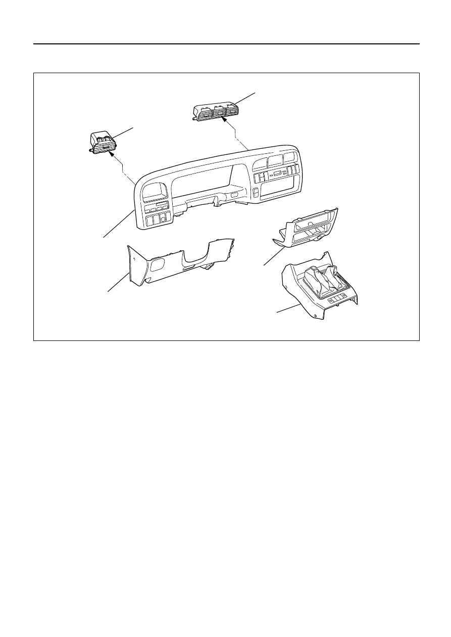
Removal Steps
1. Front console assembly
2. Lower cluster assembly
3. Instrument panel driver lower
cover assembly
4. Meter cluster assembly
5. Center vent
6. Side vent
Installation Steps
To install, follow the removal steps in the
reverse order.
CENTER AND/OR SIDE VENT
6
5
3
1
2
4
This illustration is based on LHD
740RW168
HEATING AND VENTILATION 1A – 23
INSTALLATION
To install, follow the removal steps in the reverse order.
REMOVAL
1. Front console assembly
2. Lower cluster assembly
3. Instrument panel driver lower cover assembly
4. Meter cluster assembly
•
Refer to Section 10 “BODY” for INSTRUMENT
PANEL ASSEMBLY removal procedure.
5. Center vent
•
Remove screws and the center vent from center
cluster while prying up the center vent catch
portions.
6. Side vent
•
Remove screws and the side vent from center
cluster while prying up the side vent catch
portions.
1A – 24 HEATING AND VENTILATION
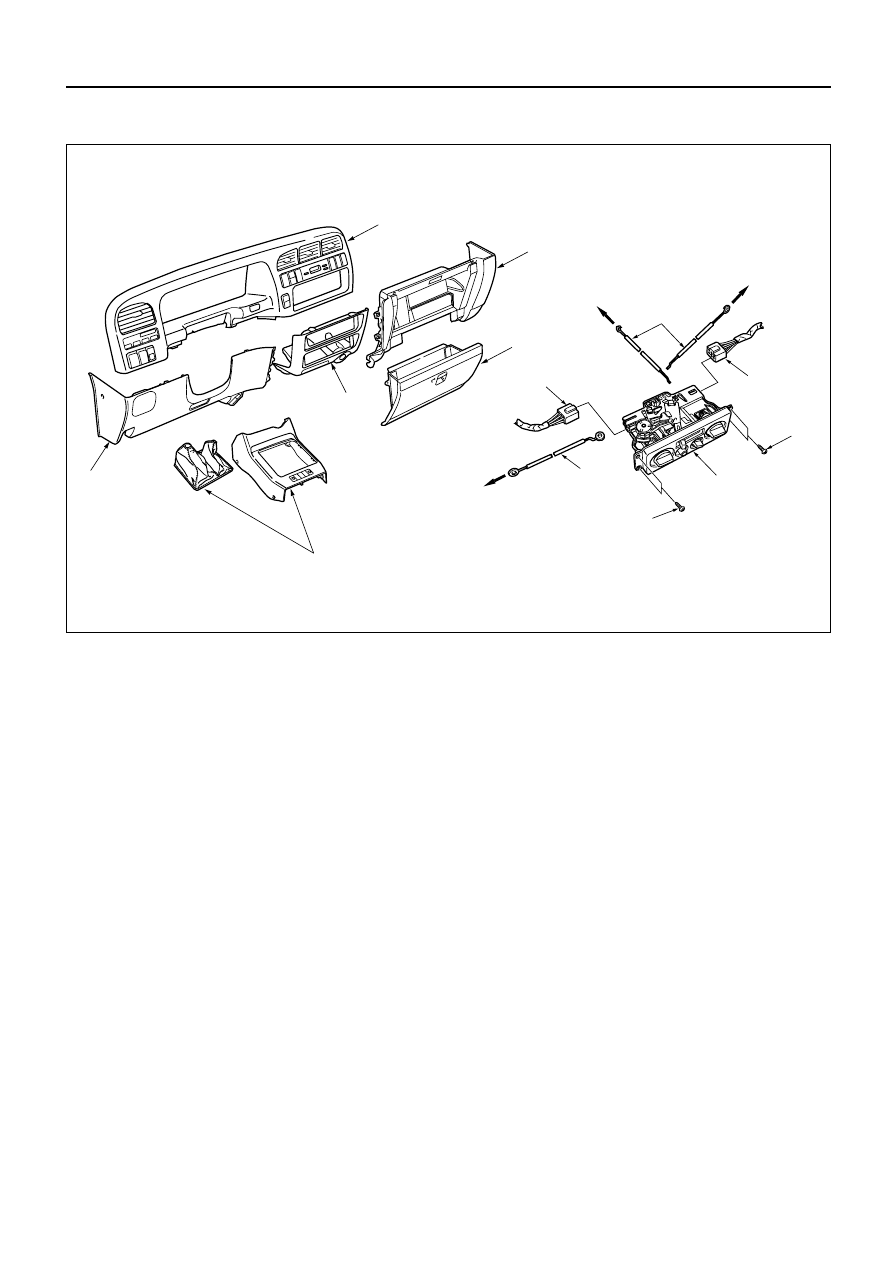
Removal Steps
1. Center console assembly
2. Lower cluster assembly
3. Glove box
4. Instrument panel passenger lower
cover assembly
5. Instrument panel driver lower cover
assembly
6. Meter cluster assembly
7. Attaching screws
8. Fan switch and air conditioning switch
connector
9. Control lever assembly
10. Control cable
CONTROL LEVER ASSEMBLY AND/OR CONTROL CABLES
6
1
5
2
10
7
7
8
8
9
10
To Mode control link
To Temp control link
To Blower assembly
4
3
Installation Steps
To install, follow the removal steps in
the reverse order.
This illustration is based on LHD
HEATING AND VENTILATION 1A – 25
REMOVAL
Preparation:
Disconnect the battery ground cable
1. Front console assembly
2. Lower cluster assembly
3. Glove box
4. Instrument panel passenger lower cover
5. Instrument panel driver lower cover
6. Meter cluster assembly
Refer to Section 10 “BODY” for INSTRUMENT PANEL
ASSEMBLY removal procedure.
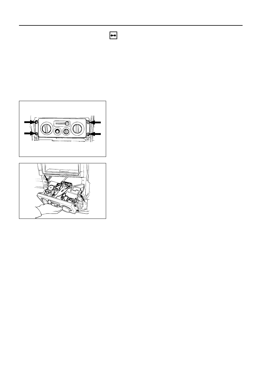
7. Attaching Screws
Remove the 4 attaching screws and disconnect the
control lever cables at heater unit and blower
assembly.
8. Fan Switch and A/C Switch Connector
Pull the control lever assembly out and disconnect
the connectors.
9. Control Lever Assembly
10. Control Cable
Нет комментариевНе стесняйтесь поделиться с нами вашим ценным мнением.
Текст