Opel Frontera UBS. Service manual — part 2561
AUTOMATIC TRANSMISSION (AW30-40LE)
7A–107
DISASSEMBLY, INSPECTION AND
REASSEMBLY OF MINOR COMPONENTS
The instructions here are organized so that you work on only
one component group at a time.
This will help avoid confusion from similar-looking parts of
different subassemblies being on your workbench at the same
time.
The component groups are inspected and repaired from the
converter housing side.
As much as possible, complete the inspection, repair and
reassembly before proceeding to the next component group. If
a component group cannot be reassembled because parts are
being ordered, be sure to keep all parts of that group in a
separate container while proceeding with disassembly,
inspection, repair and reassembly of other component groups.
Recommended ATF type BESCO ATF II or III.
GENERAL CLEANING NOTES:
1. All disassembled parts should be washed clean and any
fluid passages and holes blown through with compressed
air.
2. When using compressed air to dry parts, always aim away
from yourself to prevent accidentally spraying automatic
transmission fluid in your face.
3. The recommended automatic transmission fluid should be
used for cleaning.
PARTS ARRANGEMENT:
1. After cleaning, the parts should be arranged in proper order
to allow performing inspection, repairs, and reassembly
with efficiency.
2. When disassembling a valve body, be sure to keep each
valve together with the corresponding spring.
3. New brakes and clutches that are to be used for
replacement must be soaked in transmission fluid for at
least thirty before assembly.
GENERAL ASSEMBLY:
1. All oil seal rings, clutch discs, clutch plates, rotating parts,
and sliding surfaces should be coated with transmission
fluid prior to reassembly.
2. All gaskets and rubber O-rings should be replaced.
3. Make sure that ends of a snap ring are not aligned with one
of the cutouts and are installed in the groove correctly.
4. If a worn bushing is to be replaced, the subassembly
containing that bushing must be replaced.
5. Check thrust bearings and races for wear or damage.
Replace if necessary.
6. Use petroleum jelly or vaseline to keep parts in place.
7A–108
AUTOMATIC TRANSMISSION (AW30-40LE)
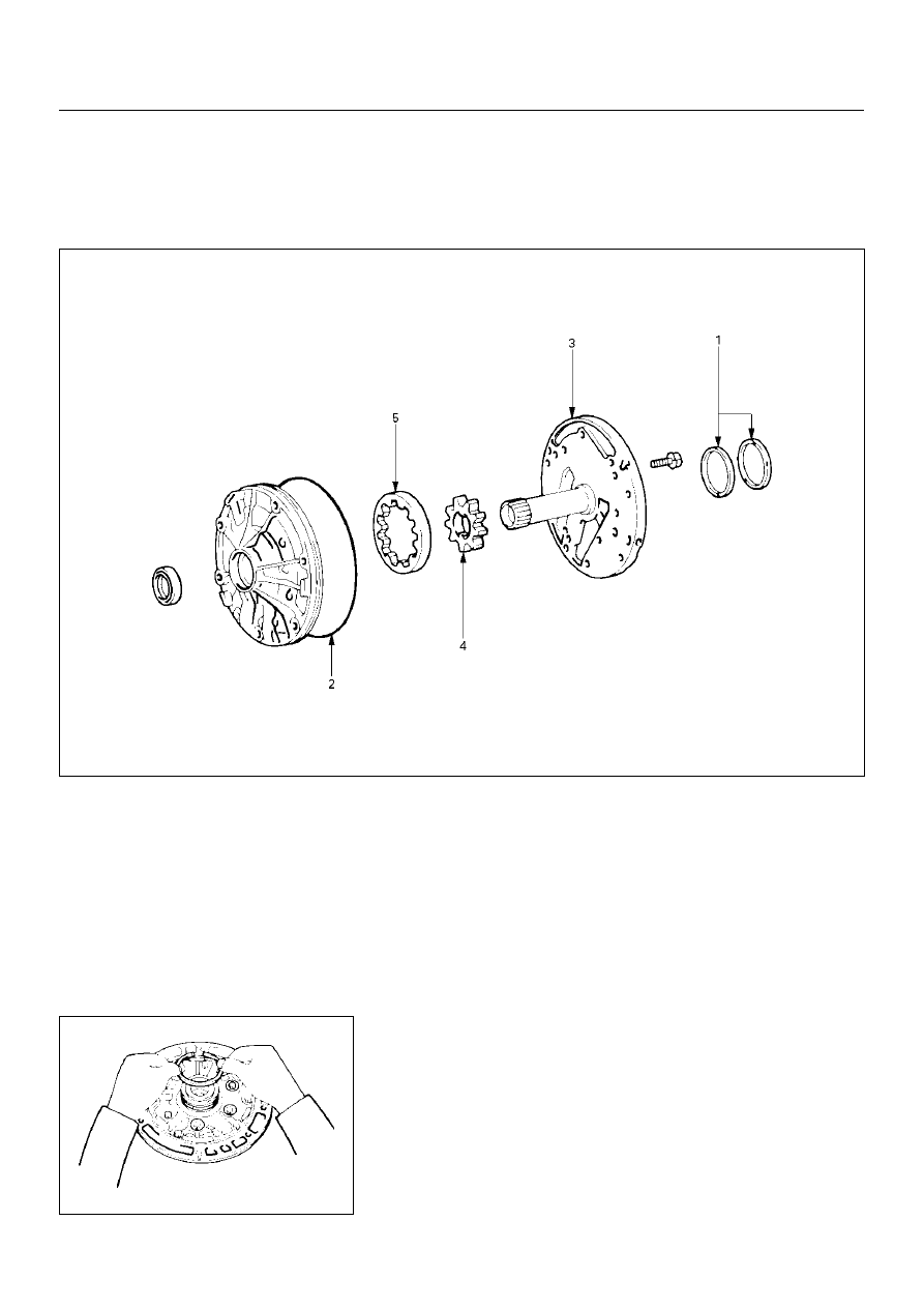
OIL PUMP
DISASSEMBLY
241RY00004
241RY00005
Important operations
1. Oil seal ring
Use torque converter as work stand.
Remove 2 oil seal rings from stator shaft.
2. O-ring
Remove O-ring.
Disassembly steps
▲
1. Oil seal ring
▲
2. O-ring
▲
3. Stator shaft
4. Oil pump drive gear
5. Oil pump driven gear
AUTOMATIC TRANSMISSION (AW30-40LE)
7A–109
241RY00006
241RY00007
241RY00008
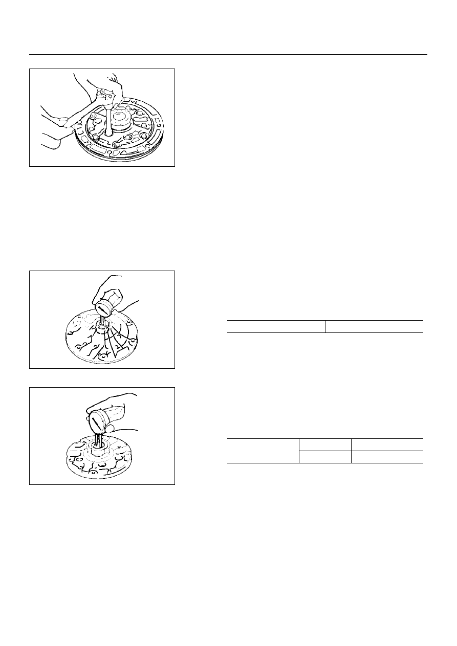
3. Stator shaft
Remove 13 bolts, and then remove the stator shaft from oil
pump body.
Then remove drive and driven gear.
INSPECTION AND REPAIR
Make necessary correction or parts replacement if wear,
damage or any abnormal conditions are found through
inspection.
Check oil pump body bushing
Using a dial indicator, measure the inside diameter of the
oil pump body bushing.
If the inside diameter is greater than the maximum, replace
the oil pump body.
Check stator shaft bushing
Using a dial indicator, measure the inside diameter of the stator
shaft bushing.
If the inside diameter is greater than maximum, replace the
stator shaft.
mm (in.)
Maximum inside diameter
38.19 (1.5035)
mm (in.)
Maximum inside
diameter
Front side
21.58 (0.8496)
Rear side
27.08 (1.0661)
7A–110
AUTOMATIC TRANSMISSION (AW30-40LE)
241RY00009
241RY00010
241RY00011
241RY00012
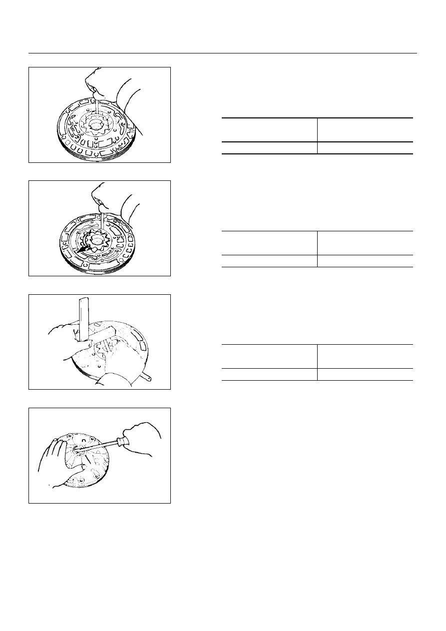
Check tip clearance of both gears
Measure between the gear teeth and the cresent-shaped
part of the pump body.
If the tip clearance is greater than the maximum, replace
the drive gear, driven gear or pump body.
Check body clearance of driven gear
Push the driven gear to one side of the body.
Use a feeler gauge, measure the clearance.
If the body clearance is greater than the maximum, replace
the drive gear, driven gear or pump body.
Check side clearance of both gears
Using a steel straightedge and a feeler gauge, measure the
side clearance of both gears.
If the side clearance is greater than the maximum, replace
the drive gear, driven gear or pump body.
Check oil seal
Check for wear, damage or cracks.
If necessary, replace oil seal.
Pry off the oil seal with a screwdriver.
mm (in.)
Standard tip clearance
0.11–0.14
(0.0043–0.0055)
Maximum tip clearance
0.3 (0.012)
mm (in.)
Standard body clearance
0.07–0.15
(0.0028–0.0059)
Maximum body clearance
0.3 (0.012)
mm (in.)
Standard side clearance
0.02–0.05
(0.0008–0.0020)
Maximum side clearance
0.1 (0.004)
Нет комментариевНе стесняйтесь поделиться с нами вашим ценным мнением.
Текст