Opel Frontera UBS. Service manual — part 1126
6A–31
ENGINE MECHANICAL
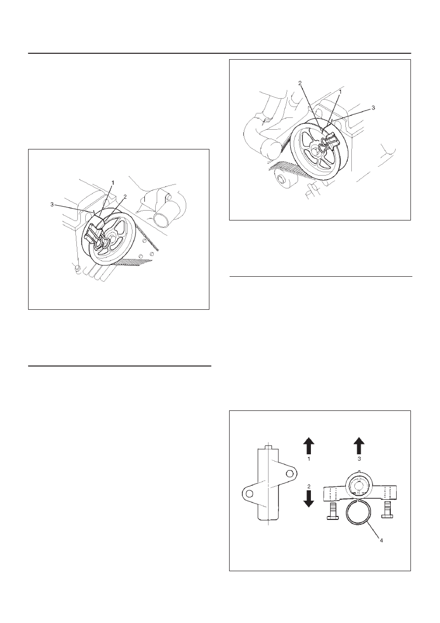
2. Align the alignment mark on the RH bank
camshaft drive gear pulley (2) to the alignment
mark of the cylinder head cover RH (3).
3. Align the alignment mark (white line) on the timing
belt (1) with alignment mark on the RH bank
camshaft drive gear pulley (2) (on the left side as
viewed from the front of the vehicle) and put the
timing belt on the camshaft drive gear pulley.
Secure the belt with a double clip or equivalent
clip.
014RW00004
Legend
(1) Alignment Mark on Timing Belt (White line).
(2) Alignment Mark on Camshaft Drive Gear
Pulley.
(3) Alignemnt Mark on Cylinder Head Cover RH.
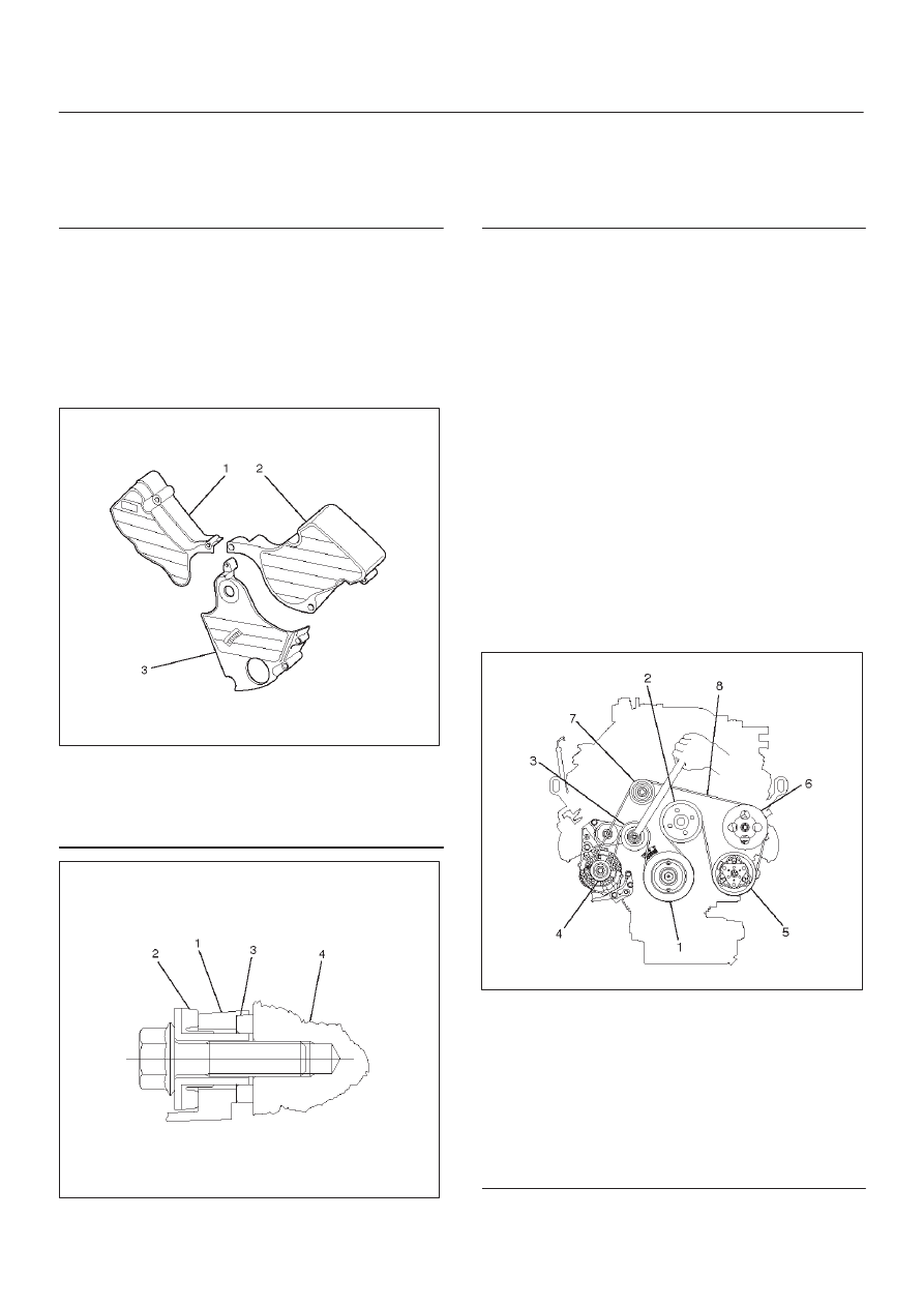
4. Align the alignment mark on the LH bank
camshaft drive gear pulley (2) to the alignment
mark of the cylinder head cover LH (3).
5. Align the alignment mark (white line) on the timing
belt (1) with the alignment mark on the LH bank
camshaft drive gear pulley (2).
When aligning the timing marks, use a wrench to
turn the camshaft drive gear pulley, then set the
timing mark between timing belt and camshaft
drive gear pulley and put the timing belt on the
camshaft drive gear pulley.
Secure the belt with a double clip or equivalent
clip.
NOTE: It is recommended for easy installation that the
belt be secured with a double clip or equivalent clip after
it is installed the timing belt to each pulley.
014RW00005
Legend
(1) Alignment Mark on Timing Belt (White line).
(2) Alignment Mark on Camshaft Drive Gear
Pulley.
(3) Alignemnt Mark on Cylinder Head Cover LH.
6. Install crankshaft pulley temporarily and tighten
center bolt by hand (do not use a wrench).
Turn the crankshaft pulley clockwise to give some
belt slack between the crankshaft timing pulley
and the RH bank camshaft drive gear pulley.
2. Install pusher and tighten bolt to the specified torque.
Torque : 25 N·m (2.5 Kg·m/18 lb ft)
1. Install the pusher while pushing the tension pulley
to the belt.
2. Pull out pin from the pusher.
NOTE: When reusing the pusher, press the pusher with
approximately 100Kg to retract the rod, and insert a pin
(1.4 mm piano wire).
014RW011
6A–32
ENGINE MECHANICAL
Legend
(1) Up Side
(2) Down Side
(3) Direction for Installation
(4) Locking Pin
3. Remove double clips or equivalent clips, from
timing belt pulleys.
Turn the crankshaft pulley clockwise by two turns.
3. Install timing belt cover.
Remove crankshaft pulley that was installed in step
1 item 5.
Tighten bolts to the specified torque.
Torque: 19 N·m (1.9 Kg·m/14 lb ft)
020RW004
Legend
(1) Timing Belt Cover RH
(2) Timing Belt Cover LH
(3) Timing Belt Cover Lower
020RW003
Legend
(1) Timing Belt Cover
(2) Rubber Bushing
(3) Sealing Rubber
(4) Cylinder Body
4. Install crankshaft pulley using 5–8840–0133–0, hold
the crankshaft pulley and tighten center bolt to the
specified torque.
Torque : 167 N·m (17.0 Kg·m/123 lb ft)
5. Install fan pulley bracket and tighten fixing bolts to the
specified torque.
Torque : 22 N·m (2.2 Kg·m/16 lb ft)
6. Install power steering pump assembly and tighten to
the specified torque.
Torque :
M8 bolt : 22 N·m (2.2 Kg·m/16 lb ft)
M10 bolt : 46 N·m (4.7 Kg·m/34 lb ft)
7. Install cooling fan assembly and tighten bolts/nuts to
the specified torque.
Torque : 22 N·m (2.2 Kg·m/16 lb ft) for fan pulley
and fan bracket.
Torque : 10 N·m (1.0 Kg·m/88.5 lb in) for fan and
clutch assembly.
8. Move drive belt tensioner to loose side using wrench,
then install drive belt to normal position.
850RW001
Legend
(1) Crankshaft Pulley
(2) Cooling Fan Pulley
(3) Auto Tensioner
(4) Generator
(5) Air Conditioner Compressor
(6) Power Steering Oil Pump
(7) Idle Pulley
(8) Drive Belt
9. Install radiator upper fan shroud.
10. Install air cleaner assembly.
6A–33
ENGINE MECHANICAL
Camshaft
Removal
1. Disconnect battery ground cable.
2. Remove crankshaft pulley.
D
Refer to removal procedure for Crankshaft Pulley in
this manual.
3. Remove timing belt.
D
Refer to removal procedure for Timing Belt in this
manual.
4. Remove cylinder head cover LH.
D
Refer to removal procedure for Cylinder Head
Cover LH in this manual.
5. Remove cylinder head cover RH.
D
Refer to removal procedure for Cylinder Head
Cover RH in this manual.
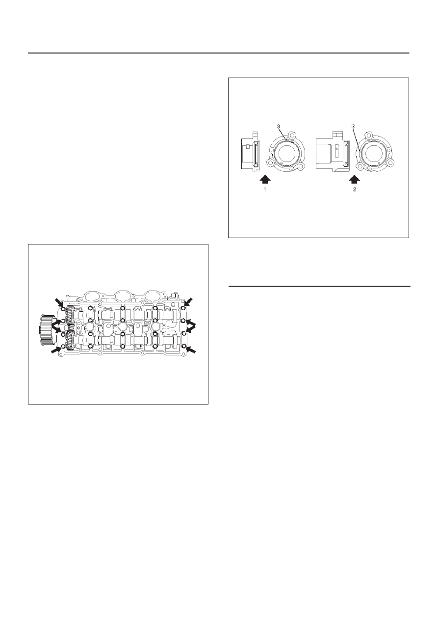
6. Remove twenty fixing bolts from inlet and exhaust
camshaft bracket on one side bank, then camshaft
brackets.
014RW027
7. Remove camshaft assembly.
8. Remove fixing bolt for camshaft drive gear pulley.
9. Remove three fixing bolts from camshaft drive gear
retainer, then camshaft drive gear assembly.
014RW026
Legend
(1) Right Bank
(2) Left Bank
(3) Timing Mark on Retainer
Installation
1. Install camshaft drive gear assembly and tighten
three bolts to the specified torque.
Torque : 10 N·m (1.0 Kg·m/89 lb in)
2. Tighten bolt for camshaft drive gear assembly pulley
to the specified torque.
Torque : 98 N·m (10.0 Kg·m/72 lb ft)
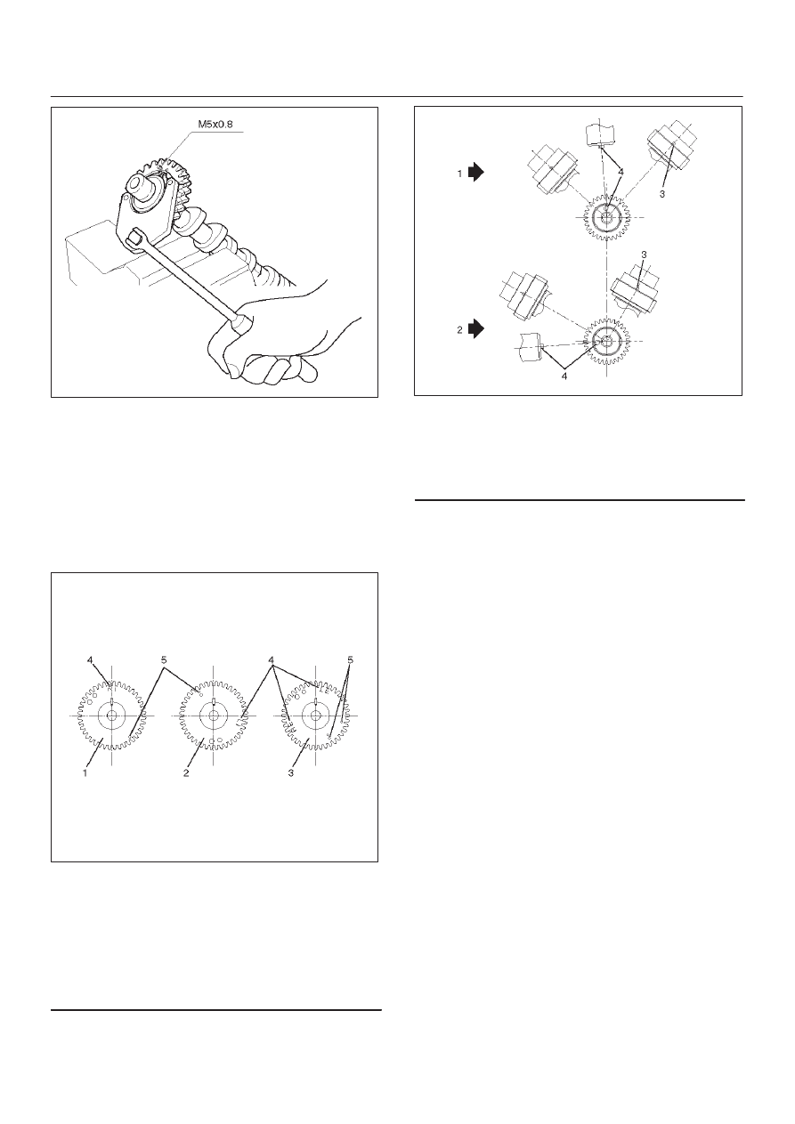
3. Tighten sub gear setting bolt.
1. Use the 5–8840–2443–0 gear spring lever to turn
sub gear to right direction until it aligns with the M5
bolt hole between camshaft driven gear and sub
gear.
2. Tighten the M5 bolt to a suitable torque to prevent
the sub gear from moving.
6A–34
ENGINE MECHANICAL
014RW041
4. Install camshaft assembly and camshaft brackets,
tighten twenty bolts on one side bank to the specified
torque.
1. Apply engine oil to camshaft journal and bearing
surface of camshaft bracket.
2. Align timing mark on intake camshaft (one dot for
right bank, two dot for left bank) and exhaust
camshaft (one dot for right bank, two dots for left
bank) to timing mark on camshaft drive gear (one
dot).
014RW020
Legend
(1) Intake Camshaft Timing Gear for Right Bank
(2) Intake Camshaft Timing Gear for Left Bank
(3) Exhaust Camshaft Timing Gear
(4) Discrimination Mark
(LI: Left bank intake, RI: Right bank intake)
(LE: Left bank exhaust, RE: Right bank
exhaust)
014RW023
Legend
(1) Right Bank Camshaft Drive Gear
(2) Left Bank Camshaft Drive Gear
(3) Timing Mark on Drive Gear
(4) Dowel Pin
Нет комментариевНе стесняйтесь поделиться с нами вашим ценным мнением.
Текст