Opel Frontera UBS. Service manual — part 150
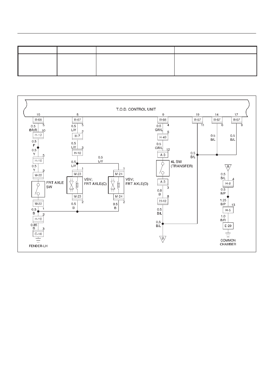
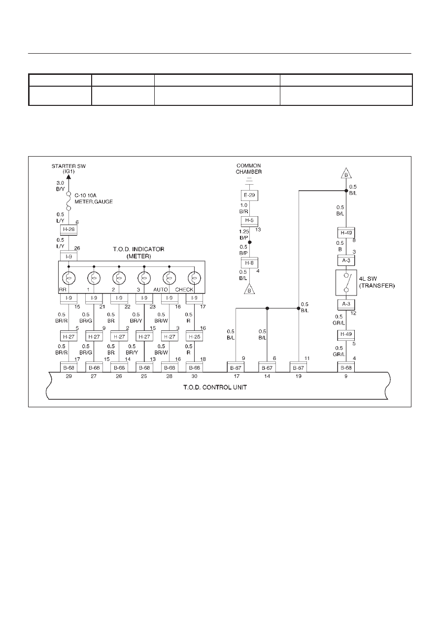
DRIVE LINE CONTROL SYSTEM (TOD)
4B2–52
Check flow
Trouble code
Phenomenon
Standard
12
32
The on/off signal (ADC) line of the
shift on the fly system (front hub) is
broken, or the line is short-circuited
to the battery.
—
NOTE: The on/off signal line of the shift on the fly system
is broken, or the line is short–circuited to the battery.
D04RW058

4B2–53
DRIVE LINE CONTROL SYSTEM (TOD)
Step
Action
Yes
No
1
1. Turn off the starter switch.
2. Disconnect the ECU connector from ECU.
Is the continuity established between terminals (B–67)5 and
(B–67)11?
Go to Step 2
The harness is
broken. Repair
the circuit.
Go to Step 3
2
Does the voltage between terminals 5 and 19 indicate 0V?
Go to Step 3
The battery is
short-circuited.
Repair the circuit.
Go to Step 4
3
1. Turn off the starter switch.
2. Connect ECU connector.
3. Turn on the starter switch.
4. Set the transfer to the 2H mode.
Is the battery voltage observed between terminals 5 and 19?
The phenomenon
is not reproduced
Refer to
“Troubles
intermittently
observed”.
Go to Step 4
The ECU has
failed. Replace
the ECU.
Go to Step 4
4
1. Check that all the parts are mounted.
2. Clear the trouble code.
Is this step complete?
Repeat the
“Diagnosis Flow”.
Return to Step 4
DRIVE LINE CONTROL SYSTEM (TOD)
4B2–54
Check flow
Trouble code
Phenomenon
Standard
13
33
The ADC line is short-circuited to
GND.
—
NOTE:
D
The on/off signal line of the shift on the fly system is
short–circuited to GND.
D
The system enters into the fail-safe mode because of
fusing or system protection.
(If a short–circuit is observed on GND, the output to
the on/off signal line becomes 0V.)
D04RW059

4B2–55
DRIVE LINE CONTROL SYSTEM (TOD)
Step
Action
Yes
No
1
1. Turn off the starter switch.
2. Disconnect the ECU connector from ECU.
Does the resistance between terminals 5 and 19 meet the
standard, R = 21
±
4 ohms?
The phenomenon
is not
reproduced.
Refer to
“Troubles
intermittently
observed”.
Go to Step 4
Go to Step 2
2
Is the resistance between terminals 5 and 19 R<2 ohms?
The signal line
circuit of the shift
on the fly system
is short-circuited
to GND. Repair
the circuit.
Go to Step 3
Go to Step 3
3
Is the resistance between terminals 5 and 19 R= 9
±
7ohms?
The signal line
circuit of the shift
on the fly system
is layer
short-circuited*.
Replace the valve
(VSV).
Go to Step 3
Go to Step 4
4
1. Check that all the parts are mounted.
2. Clear the trouble code.
Is this step complete?
Repeat the
“Diagnosis Flow”.
Return to Step 4
*Layer short-circuit : The coil is damaged by overcurrent.
Нет комментариевНе стесняйтесь поделиться с нами вашим ценным мнением.
Текст