Opel Frontera UBS. Service manual — part 1810

RESTRAINT CONTROL SYSTEM
9J1–20
DTC 18 Passenger Deployment Loop Short To Ground
Step
Action
Yes
No
1
Was the “SRS Diagnostic System Check” performed?
Go to Step 2
Go to the “SRS
Diagnostic
System Check”
2
1. When measurements are requested in this chart use
5–8840–0285–0 DVM with correct terminal adapter from
5–8840–0385–0.
2. Ignition switch “OFF.”
3. Connect scan tool data link connector. follow directions as
given in the scan tool operator’s MANUAL.
4. Ignition switch “ON.”
5. Read passenger bag sense LO.
Is passenger bag sense LO less than 1.5 volts?
Go to Step 3
Go to Chart A
3
1. Ignition switch “OFF.”
2. Disconnect passenger air bag assembly yellow 2–pin
connector behind the glove box assembly.
3. Leave driver air bag assembly connected.
4. Connect SRS driver / passenger load tool 5–8840–2421–0
and appropriate adapter to passenger air bag assembly
harness connector.
5. Ignition switch “ON.”
Is DTC 18 current?
Go to Step 4
Ignition switch
“OFF”
Replace
passenger air
bag assembly
Go to Step 6
4
1. Ignition switch “OFF”.
2. Disconnect SRS driver / passenger load tool
3. Measure resistance on SDM harness connector from terminal
“15” to terminal “16” (ground).
Does 5–8840–0285–0 display “OL” (Infinite)?
Go to Step 5
Replace SRS
Harness
Go to Step 6
5
Measure resistance on SDM harness connector from terminal
“16” to terminal “6” (ground).
Does 5–8840–0285–0 display “OL” (Infinite)?
Go to Chart A
Replace SRS
Harness.
Go to Step 6
6
1. Reconnect all components and ensure all component are
properly mounted.
2. Clear diagnostic trouble codes.
Was this step finished?
Go to the “SRS
Diagnostic
system Check”
Go to Step 6

9J1–21
RESTRAINT CONTROL SYSTEM
DTC 19 Passenger Deployment Loop Short To B+
D09RW014
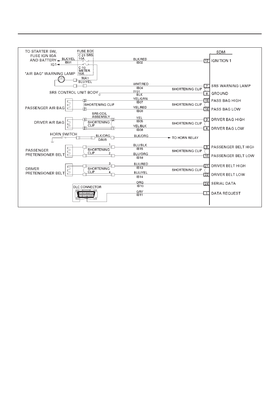
Circuit Description:
When the ignition switch is turned “ON”, the SDM will
perform tests to diagnose critical malfunctions within
itself. Upon passing these tests, “Ignition 1”, and
deployment loop voltages are measured to ensure they
are within their respective normal voltage ranges.
The SDM monitors the voltages at “Driver Bag Low”
terminal “4” and “Passenger Bag Low” terminal “16” to
detect short to B+ in the air bag assembly circuits.
DTC Will Set When:
“Ignition 1” is within the normal operating voltage range.
Once these conditions are met and the voltage at
“Passenger Bag Low” is above a specified value, DTC 19
will set. This test is run once each ignition cycle and
“Continuous Monitoring”.
Action Taken:
SDM turns “ON” the “AIR BAG” warning lamp and sets
DTC 19 and also DTC 71.
DTC Will Clear When:
The SDM is replaced.
DTC Chart Test Description:
Number(s) below refer to step number(s) on the
diagnostic chart:
2. This test determines whether the malfunction is in
the SDM.
3. This test isolates the malfunction to one side of the
passenger air bag assembly yellow 2–pin connector
behind glove box assembly.
4. This test determines whether the malfunction is in
IB07–YEL/GRN.
5. This test determines whether the malfunction is in
IB08–YEL/RED.
Diagnostic Aids:
An intermittent condition is likely to be caused by a short
to B+ in the passenger air bag assembly circuit. Inspect
IB07–YEL/GRN and IB08–YEL/RED carefully for cutting
or chafing. If the wiring pigtail of the passenger air bag
assembly is damaged, the component must be replaced.
A careful inspection of IB07–YEL/GRN and
IB08–YEL/RED, including the passenger air bag
assembly pigtail is essential to ensure that the
replacement SDM will not be damaged.

RESTRAINT CONTROL SYSTEM
9J1–22
DTC 19 Passenger Deployment Loop Short To B+
CAUTION: When DTC 19 has been set, it is necessary to replace the SDM. Setting DTC 19 will also cause DTC
71 to set. When a scan tool “CLEAR CODES” command is issued and the malfunction is no longer present,
DTC 71 will remain current. Ensure that the short to voltage condition is repaired prior to installing a
replacement SDM to avoid damaging the SDM.
Step
Action
Yes
No
1
Perform the “SRS Diagnostic System Check”
Was the “SRS Diagnostic System Check” performed?
Go to Step 2
Repeat the “SRS
Diagnostic
System Check”
2
1. When measurements are requested in this chart use
5–8840–0285–0 DVM With correct terminal adapter from
5–8840–0385–0.
2. Ignition switch “OFF.”
3. Connect scan tool data link connector. follow directions as
given in the scan tool operator’s manual.
4. Ignition switch “ON.”
5. Read passenger bag sense LO.
Is passenger bag sense LO more than 3.5 volts?
Go to Step 3
Go to Chart A
3
1. Ignition switch “OFF”.
2. Disconnect passenger air bag assembly yellow 2–pin
connector behind the glove box assembly.
3. Leave driver air bag assembly connected.
4. Connect SRS driver / passenger load tool 5–8840–2421–0
and appropriate adapter to passenger air bag assembly
harness connector.
5. Ignition switch “ON.”
Is passenger bag sense LO more than 3.5 volts?
Go to Step 4
Ignition switch
“OFF”
Replace
passenger air
bag assembly
Go to Step 6
4
1. Ignition switch “OFF.”
2. Disconnect SDM.
3. Disconnect SRS driver / passenger load tool.
4. Measure resistance on SDM harness connector from terminal
“15” to terminal “12” (ignition).
Does 5–8840–0285–0 display “OL” (infinite)?
Go to Step 5
Replace SRS
harness
Go to Step 6.
5
Measure resistance on SDM harness connector from terminal
“16” and terminal “12” (ignition).
Does 5–8840–0285–0 display “OL” (infinite)?
Go to Chart A
replace SRS
harness
Go to Step 6
6
1. Reconnect all components ensure all component are properly
mounted.
2. Ignition switch “ON”.
Is passenger bag senslo less than 3.5 volts?
Ignition switch
“OFF”
Replace SDM
Go to Step 7
Go to Chart A
7
1. Reconnect all components ensure all component are properly
mounted.
2. Clear diagnostic trouble codes.
Was this step finished?
Repeat the “SRS
Diagnostic
System Check”
Go to Step 7
9J1–23
RESTRAINT CONTROL SYSTEM
DTC 21 Driver Deployment Loop Resistance High
D09RW014
Circuit Description:
When the ignition switch is turned “ON”, the SDM will
perform tests to diagnose critical malfunctions within
itself. Upon passing these tests, “Ignition 1”, and
deployment loop voltages are measured to ensure they
are within their respective normal voltage ranges.
The SDM then proceeds with the “Resistance
Measurement Test” “Driver Bag Low” terminal “4” is
grounded through a current sink and the driver current
source connected to “Driver Bag High” terminal “3” allows
a known amount of current to flow. By monitoring the
voltage difference between “Driver Bag High” and “Driver
Bag Low”, the SDM calculates the combined resistance
of the driver air bag assembly, SRS coil assembly,
harness wiring IB05–YEL and IB06–YEL/BLK, and
connector terminal contact.
DTC Will Set When:
The combined resistance of the driver air bag assembly,
SRS Coil assembly, harness wiring IB05–YEL and
IB06–YEL/BLK, and connector terminal contact is above
a specified value. This test run once each ignition cycle
during the “Resistance Measurement Test” when:
1. No “higher priority faults” are detected during
“Turn–ON”
2. “Ignition 1” voltage is in the specified value.
Action Taken:
SDM turns “ON” the “AIR BAG” warning lamp and sets
DTC 21.
DTC Will Clear When:
The ignition switch is turned “OFF”.
DTC Chart Test Description:
Number(s) below refer to step number(s) on the
diagnostic chart:
2. This test determines whether the malfunction is in
the SDM.
3. This test verifies proper connection of the yellow
2–pin connector at the base of the steering column.
4. This test checks for proper contact and/or corrosion
of the 2–pin connector terminals at the base of
steering column.
5. This test isolate the malfunction to one side of the
SRS coil assembly yellow 2–pin connector located
at the base of the steering column.
6. This test determines whether the malfunction is due
to high resistance in the wiring.
7. This test determines whether the malfunction is in
the SRS coil assembly or the driver air bag
assembly.
Нет комментариевНе стесняйтесь поделиться с нами вашим ценным мнением.
Текст