Opel Frontera UBS. Service manual — part 1609
8D–114
WIRING SYSTEM
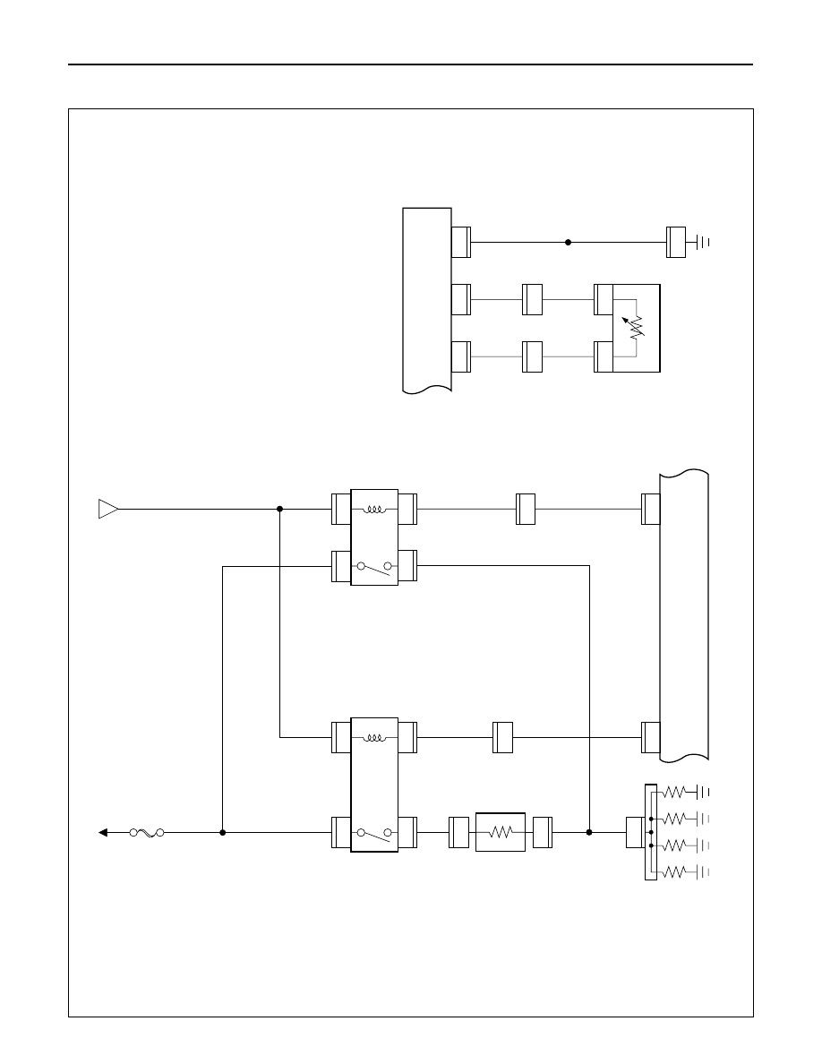
Circuit Diagram (LHD)-2
DROPPING
RESIST
OR
GLOW
PLUG
GLOW
RELA
Y
-2
QOS
III
CONTROL
UNIT
GLOW
RELA
Y
-1
C-66
12
H-42
16
1
1
C-60
C-59
3.0
R/W
3.0
B/Y
3.0
B/R
0.5
B/G
0.5
B/G
0.85
B/Y
FL-5 50A
GLOW
C-53
1
C-59
2
1
C-54
BA
TT
.(+)
C-55
1
2
C-55
A
C-66
5
H-41
7
3.0
B/R
0.5
B/L
0.5
B/L
0.85
B/Y
0.85
B/Y
3.0
R/W
C-51
1
C-51
C-52
1
2
2
C-52
12
E-41
E-41
QOS THERMO
SENSOR
(ENGINE)
QOS III CONTROL
UNIT
C-16
0.5
B
0.5
Y
0.5
Y
0.5
B/Y
0.5
B
8
C-66
10
FENDER
-LH
C-66
8
C-66
4
H-4
8
H-4
12
D08RW981
WIRING SYSTEM
8D–115
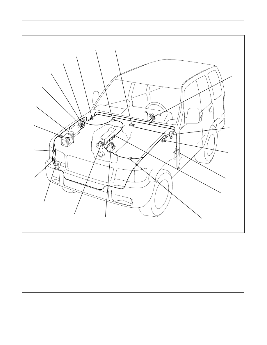
Parts Location (LHD)
Legend
(1) C-66
(2) I-9
(3) H-7, H-8, H-24, H-25
(4) C-16
(5) Fuse Box
(6) Glow Plug
×
4
(7) H-4, H-5
(8) E-37
(9) E-41
(10) Dropping Resistor
(11) C-59
(12) H-41, H-42
(13) H-3
(14) Relay and Fuse Box (X-17)
(15) Glow Relay-1 (C-51, C-52)
(16) Glow Relay-2 (C-53, C-54, C-55)
(17) C-39
(18) H-13
(19) C-60
1
2
3
4
5
6
7
8
9
10
11
12
13
14
15
16
17
18
19
D08RWA26
8D–116
WIRING SYSTEM
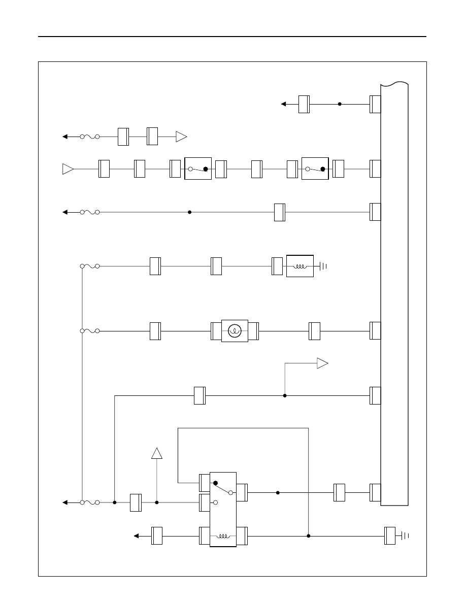
QOS and EGR System (4JG2)
General Description
The circuit consists of the starter switch, QOS/EGR
control unit, glow relay, charge relay, fuel cut
solenoid, dropping resistor, thermo sensor, glow
indicator light (meter), glow plug, vehicle speed
sensor, tacho sensor, throttle position sensor, EVRV
and VSV; EGR.
The engine coolant temperature at the time of the
engine start-up is sensed by the thermo sensor to
change the glow time so that the optimum starting
conditions can always be obtained.
The idling speed just after the engine start-up can
also be placed in the most suitable conditions in
accordance with the coolant temperature by the
operation of the delay timer.
The indicator timer is activated upon the starter
switch turned to the ON position, and the indicator
light comes on for as much time as suitable for the
engine coolant temperature at the time of the
engine start-up.
EGR system controls the information of NOx by
returning a small amount of exhaust gas from the
intake manifold to the combustion chamber
through the EGR valve.
WIRING SYSTEM
8D–117
Circuit Diagram (RHD)-1
0.5
B
0.5
W/G
0.85
W/G
0.5
B
0.5
B/Y
0.5
B/Y
0.85
B/Y
0.5
L/Y
0.5
L/Y
0.5
P/W
0.85
B/O
0.85
B/O
0.85
B/O
0.3
P/W
0.85
B/Y
0.85
B/Y
0.85
B/Y
3.0
B/Y
C-8 15A
ENGINE
CHARGE
RELA
Y
GLOW
INDICA
T
O
R
LIGHT
(METER)
FUEL
CUT
SOLENOID
AMBIENT
THERMO
SW
QWS
THERMO SW
(ENGINE)
0.85
W/L
QOS/EGR CONTROL
UNIT
C-66
18
C-66
9
C-66
5
C-66
17
C-66
20
C-66
16
C-39
1
X-17
2
I-9
15
H-41
12
H-9
14
X-17
3
X-17
5
H-3
3
1
X-17
26
I-9
4
X-17
FENDER-RH
ST
AR
TER SW
(IG1)
AC GENERA
T
O
R
(L)
C-10 10A
METER, GAUGE
C-9 15A
FUEL
CUT
A
19
H-15
3.0
W/G
0.5
W/R
0.5
BR
0.5
BR
0.5
BR
0.5
LG/Y
0.5
G/B
0.5
G/W
0.5
W/R
C-1 10A
ST
AR
TER
RELA
Y
ST
AR
TER SW
(ST)
4
H-7
1
E-40
11
H-4
2
C-74
3.0
L/R
0.5
BR
0.5
BR
0.5
BR
C-20 10A
AIR CON
HEA
TER &
A/C
RELA
Y(4)
16
H-26
0.5
LG/W
0.3
LG/W
VEHICLE SPEED
SENSOR(3)
15
H-5
12
H-7
6
H-26
H-5
7
H-41
2
H-4
7
E-40
2
7
E-37
1
H-7
B
C
C
H-16
7
C-74
1
D08RW695
Нет комментариевНе стесняйтесь поделиться с нами вашим ценным мнением.
Текст