Opel Frontera UBS. Service manual — part 2346
6E–420
6VE1 3.5 ENGINE DRIVEABILITY AND EMISSIONS
Diagnostic Trouble Code (DTC) P1404 EGR Stuck Closed
D06R200075
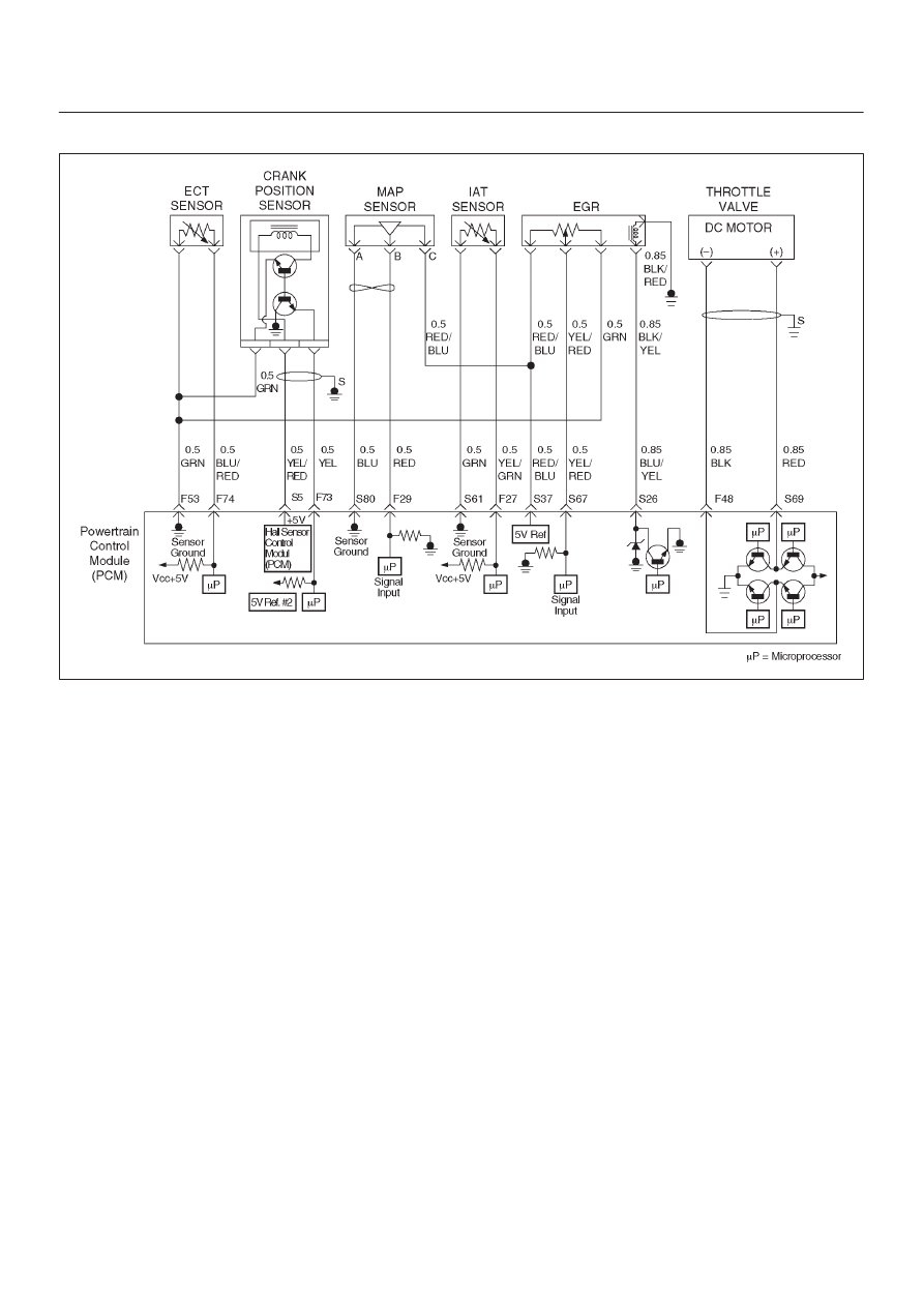
Circuit Description
The powertrain control module (PCM) monitors the EGR
valve pintle position input to ensure that the valve
responds properly to commands from the PCM, and to
detect a fault if current pintle zero position is different from
the learned zero position. If the PCM detects a pintle
position signal indicates more than 30 % different
between current zero position and the learned zero
position for more than 5 seconds, and this condition exists
3 times during trip, then the PCM will set DTC P1404.
Conditions for Setting the DTC
D
Ignition voltage is between 11 and 16 volts.
D
Intake Air temp is more than 3
°
C.
D
Desired EGR position is more than 3 %.
D
Difference of EGR pintle position between current and
the learned zero is more than 30 % for more than 5
seconds, and exists three times to the above condition
during a trip the PCM will set DTC 1404. Then it trigger
the PCM light on.
Action Taken When the DTC Sets
D
The PCM will illuminate the malfunction indicator lamp
(MIL) after consecutive 2nd trip in which the fault is
detected.
D
The PCM will store conditions which were present
when the DTC was set as Freeze Frame and in Failure
Records data.
Conditions for Clearing the MIL/DTC
D
The PCM will turn the MIL “OFF” on the third
consecutive trip cycle during which the diagnostic has
been run and the fault condition is no longer present.
D
A history DTC P1404 will clear after 40 consecutive
warm-up cycles have occurred without a fault.
D
DTC P1404 can be cleared by using the Tech 2 “Clear
Info” function or by disconnecting the PCM battery
feed.
Diagnostic Aids
Check for the following conditions:
D
Excessive carbon deposit on EGR valve shaft and/or
foreign material may cause the EGR valve not to fully
seat. The carbon deposit may occur by unusual port
operation. Remove foreign material and/or excessive
carbon deposit on EGR valve shaft and to allow the
EGR valve to be fully seated.
D
Poor connection or damaged harness – Inspect the
wiring harness for damage.
Reviewing the Failure Records vehicle mileage since the
diagnostic test last failed may help determine how often
the condition that caused the DTC to be set occurs. This
may assist in diagnosing the condition.

6E–421
6VE1 3.5L ENGINE DRIVEABILITY AND EMISSIONS
DTC P1404 – EGR Stuck Closed
Step
Action
Value(s)
Yes
No
1
Was the “On-Board Diagnostic (OBD) System Check”
performed?
—
Go to
Step 2
Go to
OBD
System
Check
2
1. Ignition “ON”, engine “OFF”, review and record
Tech 2 Failure Records Data.
2. Operate the vehicle within Failure Records
conditions as noted.
3. Using a Tech 2, monitor “DTC inf.” for DTC P1404
until the DTC P1404 test runs. Note the result.
Does the Tech 2 indicates DTC P1404 failed this
ignition?
—
Go to
Step 3
Check the
Procedure
Refer to
Diagnostic
Aids
3
1. Disconnect the EGR valve harness connector.
2. Inspect the EGR valve and connectors for damaged
pin or terminals.
Were there any damaged pins or terminals?
—
Go to
Step 4
Go to
Step 5
4
Repair the damaged pin or terminal.
Is the action complete?
—
Verify repair
—
5
1. Remove EGR valve from Engine.
2. Inspect EGR valve for any excessive carbon
deposit on EGR shaft.
3. Inspect for any foreign material inside of EGR valve.
Was excessive carbon deposit on EGR valve shaft
and/or foreign material in EGR valve ?
—
Go to
Step 6
Go to
Step 7
6
1. Clean up EGR valve shaft and inside of EGR valve.
2. Remove foreign material from EGR valve.
3. Visually inspect damage of pintle and seat to see if it
is bent. If damaged, leakage may occur.
Was there any severe damage which affects function?
—
Go to
Step 9
Verify repair
Go to
Step 7
7
1. Install the EGR valve.
2. Ignition “OFF”.
3. Install the Tech 2.
4. Run the engine at idle.
5. On the Tech 2, select EGR Control Test.
6. Use the “UP” arrow to increase the EGR from 0% to
40%.
Did EGR work properly?
—
Verify repair
Go to
Step 8
8
1. Reset the learned zero EGR valve position.
2. Repeat step 7.
Did EGR work properly?
—
Verify repair
Go to
Step 9

6E–422
6VE1 3.5 ENGINE DRIVEABILITY AND EMISSIONS
DTC P1404 – EGR Stuck Closed
(Cont'd)
Step
No
Yes
Value(s)
Action
9
Replace the EGR valve.
Does DTC P1404 still fail “DTC” test on the Tech 2?
—
Go to
Step 10
Verify repair
10
Replace the PCM.
IMPORTANT: The replacement PCM must be
programmed. Refer to
On-Vehicle Service in
Powertrain Control Module and Sensors for
procedures.
And also refer to latest Service Bulletin.
Check to see if the Latest software is released or not.
And then Down Load the LATEST PROGRAMMED
SOFTWARE to the replacement PCM.
Is the action complete?
—
Verify repair
—
6E–423
6VE1 3.5L ENGINE DRIVEABILITY AND EMISSIONS
Diagnostic Trouble Code (DTC) P1514 TPS - MAF Correlation Error
D06RY00090
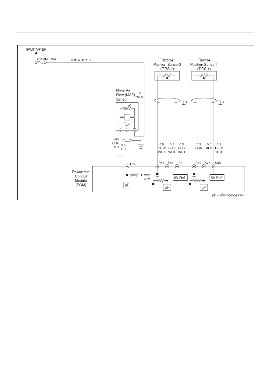
Circuit Description
D
The throttle position (TP) sensor circuit provides a
voltage signal relative to throttle blade angle.
The throttle blade angle will vary about 8 % at closed
throttle to about 92 % at wide open throttle (WOT).
D
The mass air flow (MAF) sensor measures the amount
of air which passes through it into the engine during a
given time. The powertrain Control Module (PCM)
uses the mass air flow information to monitor engine
operating conditions for fuel delivery calculations.
A large quantitiy of air entering the engine indicates
an accleration or high load situation, while a small
quantity or air indicates deceleration or idle.
The MAF sensor produces a frequency signal which
can be monitored using a Tech 2. The frequency will
vary within a range of around 4 to 7g/s at idle to
around 25 to 40g/s at maximum engine load.
Conditions for setting the DTC
D
The engine is running.
D
No MAF sensor DTCs are set.
D
Throttle actuation mode is not off.
D
MAF reading-ETC estimated air flow is less than 40g/s
for 250 failres within test 1000 test samples (15.6 m
sec).
Action Taken When the DTC Sets
D
The PCM will illuminate the malfunction indicator lamp
(MIL) the first time the fault is detected.
D
The PCM calculates an air flow value based on idle air
control valve position, throttle position, RPM and
barometric pressure.
D
The PCM will store condition which were present when
the DTC was set as Freeze Frame and in the Failure
Records data.
Conditions for Clearing the MIL/DTC
D
The PCM will turn the MIL “OFF” on the third
consecutive trip cycle during which the diagnostic has
been run and the fault condtion is no longer present.
D
A history DTC P1514 will clear after 40 cosecutive trip
cycle during which the warm up cycles have occurred
without a fault.
D
DTC P1514 can be cleared using the Tech 2 “Clear
Info” function or by disconnecting the PCM battery
feed.
Diagnostic Aids
An intermittent may be caused by the following:
D
Poor connectons.
D
Mis routed harness.
D
Rubbed through wire insulation.
D
Broken wire inside the insulation.
Check for the following conditions:
D
Poor connection at PCM - Inspect harness connectors
for backed out terminals, improper mating,broken
locks, improperly formed or damaged terminals,and
poor terminal to wire connection.
D
Damaged harness - Inspect the wiring harness for
damage. If the harness appears to be OK, observe the
Нет комментариевНе стесняйтесь поделиться с нами вашим ценным мнением.
Текст