Opel Frontera UBS. Service manual — part 1216

6E–230
ENGINE DRIVEABILITY AND EMISSIONS
DTC P0405 – EGR Low Volt
(Cont'd)
Step
No
Yes
Value(s)
Action
12
1. Ignition “ON”.
2. Backprobe with a DVM to measure voltage at PCM
sensor ground pin and pintle position pin.
Was voltage in range?
Less than
0.1 V
Go to
Step 13
Go to
Step 18
13
1. Ignition “OFF”.
2. Disconnect the EGR harness.
3. Check short circuit between EGR pintle position
circuit and EGR ground circuit.
Was any short circuit?
—
Go to
Step 14
Go to
Step 18
14
Locate and repair the short to ground in the pintle
position circuit
Is the action complete?
—
Verify repair
—
15
1. Ignition “OFF”.
2. Disconnect the PCM.
3. Ignition “ON”.
4. Measure the voltage between the EGR pintle
position circuit and ground.
Is the measured voltage near the specified value?
Less than
0.1 V
Go to
Step 17
Go to
Step 16
16
Check for a short circuit between other wires and the
pintle position circuit
Was any short circuit?
—
Repair short
circuit
Verify repair
Go to
Step 17
17
Replace the EGR valve.
Does DTC P1404 still fail “specific DTC test on Tech 2?
—
Go to
Step 18
Verify repair
18
Examine the PCM pin and terminal connection.
Was there a damaged terminal?
—
Go to
Step 4
Go to
Step 19
19
Replace the PCM.
IMPORTANT: The replacement PCM must be
programmed. Refer to
UBS 98model year Immobilizer
Workshop Manual.
Is the action complete?
—
Verify repair
—
6E–231
ENGINE DRIVEABILITY AND EMISSIONS
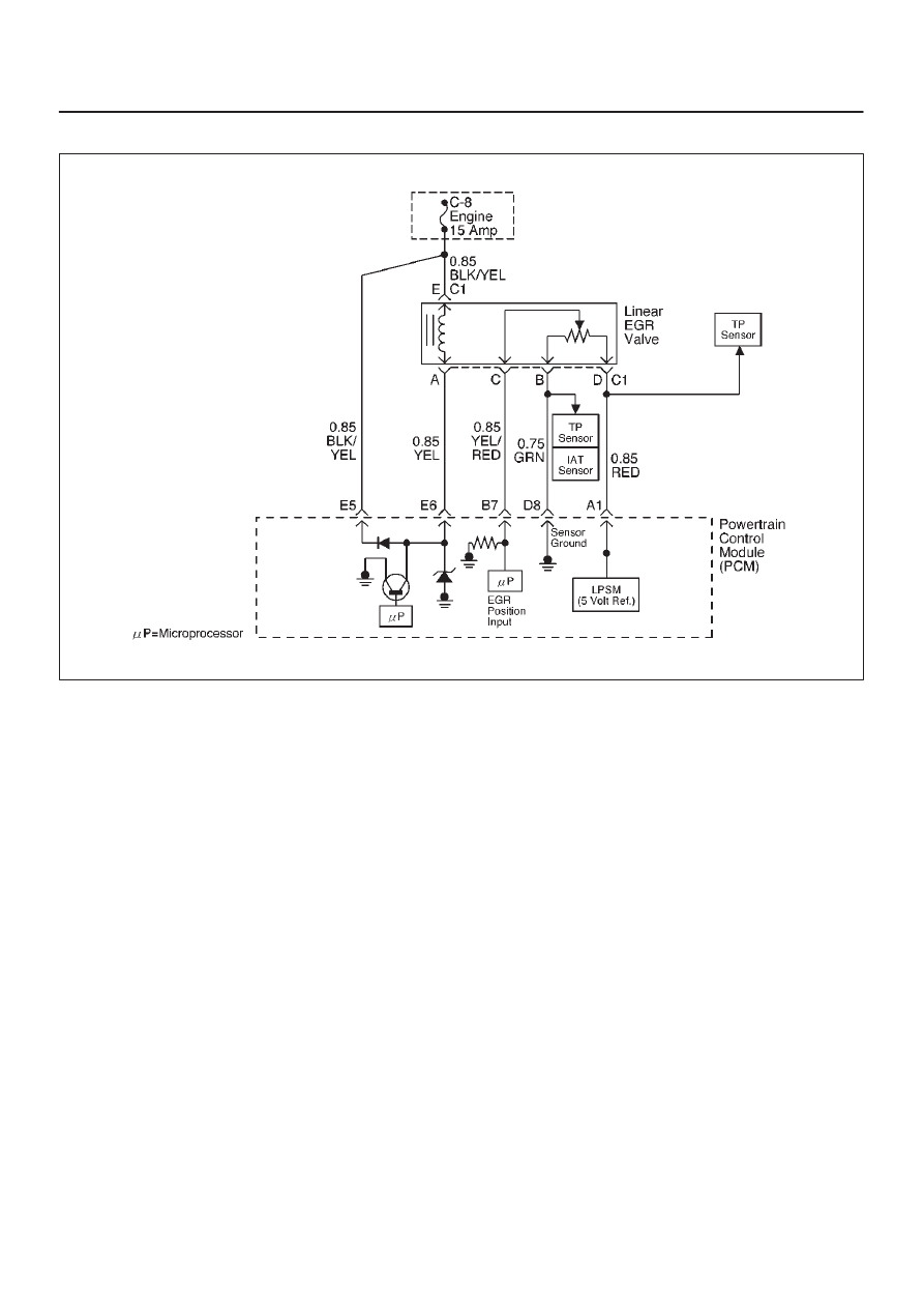
Diagnostic Trouble Code (DTC) P0406 EGR High Voltage
D06RW106
Circuit Description
The powertrain control module (PCM) monitors the EGR
valve pintle position input to ensure that the valve
responds properly to command from the PCM. If current
pintle position voltage indicates more than 4.8 V and last
more than 10 seconds, then the PCM will set DTC P0406.
Conditions for Setting the DTC
D
Ignition voltage is between 11 and 16 volts.
D
EGR pintle position output voltage is more than 4.8 volt
and last more than 10 sec.
Action Taken When the DTC Sets
D
The PCM will illuminate the malfunction indicator lamp
(MIL) as soon as failure detected.
D
The PCM will store conditions which were present
when the DTC was set as Freeze Frame and in Failure
Records data.
Conditions for Clearing the MIL/DTC
D
DTC P0404 can be cleared by using Tech 2 “Clear Info”
function or by disconnecting the PCM battery feed.
Diagnostic Aids
Check for the following conditions:
D
Poor connection or damaged harness – Inspect the
wiring harness for damage. If the harness appears to
be OK, observe the EGR actual position display on
Tech 2 while moving connectors and wiring harnesses
related to EGR valve. A change in the display will
indicate the location of the fault.

6E–232
ENGINE DRIVEABILITY AND EMISSIONS
DTC P0406 – EGR High Voltage
Step
Action
Value(s)
Yes
No
1
Was the “On-Board Diagnostic (OBD) System Check”
performed?
—
Go to
Step 2
Go to
OBD
System
Check
2
1. Ignition “ON,” engine “OFF”, review and record
Tech 2 Failure Records Data.
2. Operate the vehicle within Failure Records
conditions as noted.
3. Using Tech 2, monitor “DTC” info for DTC P0406
until the DTC P0406 test runs. Note the result.
Does Tech 2 indicates DTC P0406 failed this ignition?
—
Go to
Step 3
Refer to
Diagnostic
Aids
3
1. Disconnect the EGR valve harness connector.
2. Inspect the EGR valve and connectors for damaged
pin or terminals.
Were there any damaged pins or terminals?
—
Go to
Step 4
Go to
Step 5
4
Repair the damaged pin or terminal.
Is the action complete?
—
Verify repair
Is the action
complete?
5
1. Disconnect the EGR harness connector.
2. Ignition “ON”.
3. At the EGR valve, use a DVM to check the voltage
at the 5 volt reference wire (RED).
Did the DVM indicate the specified value?
4–6 V
Go to
Step 8
Go to
Step 6
6
1. Ignition “ON”.
2. At the PCM connector, backprobe with a DVM at the
5 volt reference for the EGR valve.
Did the DVM indicate the specified value?
4–6 V
Go to
Step 7
Go to
Step 16
7
Repair the open 5 volt reference circuit
Is the action complete?
—
Verify repair
—
8
1. Ignition “OFF”
2. Disconnect the EGR harness.
3. Use a DVM to check for an resistance between D (5
V reference) and B (Sensor Ground) at EGR sensor
terminals.
NOTE: J-35616 Connector Test Adapter Kit may be
useful for gaining access to the recessed pins on the
valve.
Was there measured resistance in range?
5 to 5 K
W
Go to
Step 9
Go to
Step 15
9
1. Ignition “OFF”.
2. Disconnect the EGR harness.
3. Use a DVM to check for an resistance between B
and C at EGR sensor terminal.
Was there open circuit?
—
Go to
Step 15
Go to
Step 10
10
1. Ignition “OFF”.
2. Disconnect the EGR harness at PCM connector.
3. Use a DVM to check for shorted wire between A1
and B7.
Was there shorted wire?
—
Go to
Step 14
Go to
Step 11

6E–233
ENGINE DRIVEABILITY AND EMISSIONS
DTC P0406 – EGR High Voltage
(Cont'd)
Step
No
Yes
Value(s)
Action
11
1. Ignition “ON”.
2. Use a DVM to backprobe at terminal C of EGR
valve for voltage.
Was measured voltage more than 4.8 V?
more than
4.8 V
Go to
Step 12
Go to
Step 12
12
1. Ignition “ON”.
2. Stay the EGR harness connected.
3. Check voltage by backproving at PCM B7 terminal.
Was voltage more than 4.8 V?
4.8 V
Go to
Step 16
Go to
Step 13
13
1. Locate short circuit at EGR harness between RED
to RED or GREEN, RED to YEL.
2. Replace EGR harness.
Is the action complete?
—
Verify repair
—
14
Replace EGR harness.
Is the action complete?
—
Verify repair
—
15
Replace the EGR valve.
Does DTC P1404 still fail “specific DTC test on Tech 2?
—
Go to
Step 16
Verify repair
16
Replace the PCM.
IMPORTANT: The replacement PCM must be
programmed. Refer to
UBS 98model year Immobilizer
Workshop Manual.
Is the action complete?
—
Verify repair
—
Нет комментариевНе стесняйтесь поделиться с нами вашим ценным мнением.
Текст