Opel Frontera UBS. Service manual — part 2412
6C – 10 ENGINE FUEL
REMOVAL
Prior to removal, be sure to confirm and record the
group code of the injector installed using Tech2.
1. Disconnect battery ground cable.
2. Remove air cleaner cover and air duct.
3. Remove intercooler.
Refer to “Intercooler” in this manual.
4. Remove PCV hose and pipe.
5. Remove cylinder head noise insulator cover.
6. Remove high pressure oil pipe.
CAUTION:
1) Sleeve nut should be loosened with cloth tied
around to prevent oil from spurting due to the
remaining pressure.
2) High oil pressure pipe should be disconnected
with cloth tied around the intake manifold glow
plug to prevent oil from flowing out of the oil
rail.
7. Loosen eye bolt of fuel pipe at fuel pump side.
NOTE: Cloth should be put around the loosened eye
bolt to prevent fuel from flowing out.
8. Remove fuel return hose at chassis side.
9. Remove PCV hose to cylinder head cover.
10. Remove cylinder head cover.
11. Drain the oil from oil rail assembly.
NOTE: Do not drop O-ring
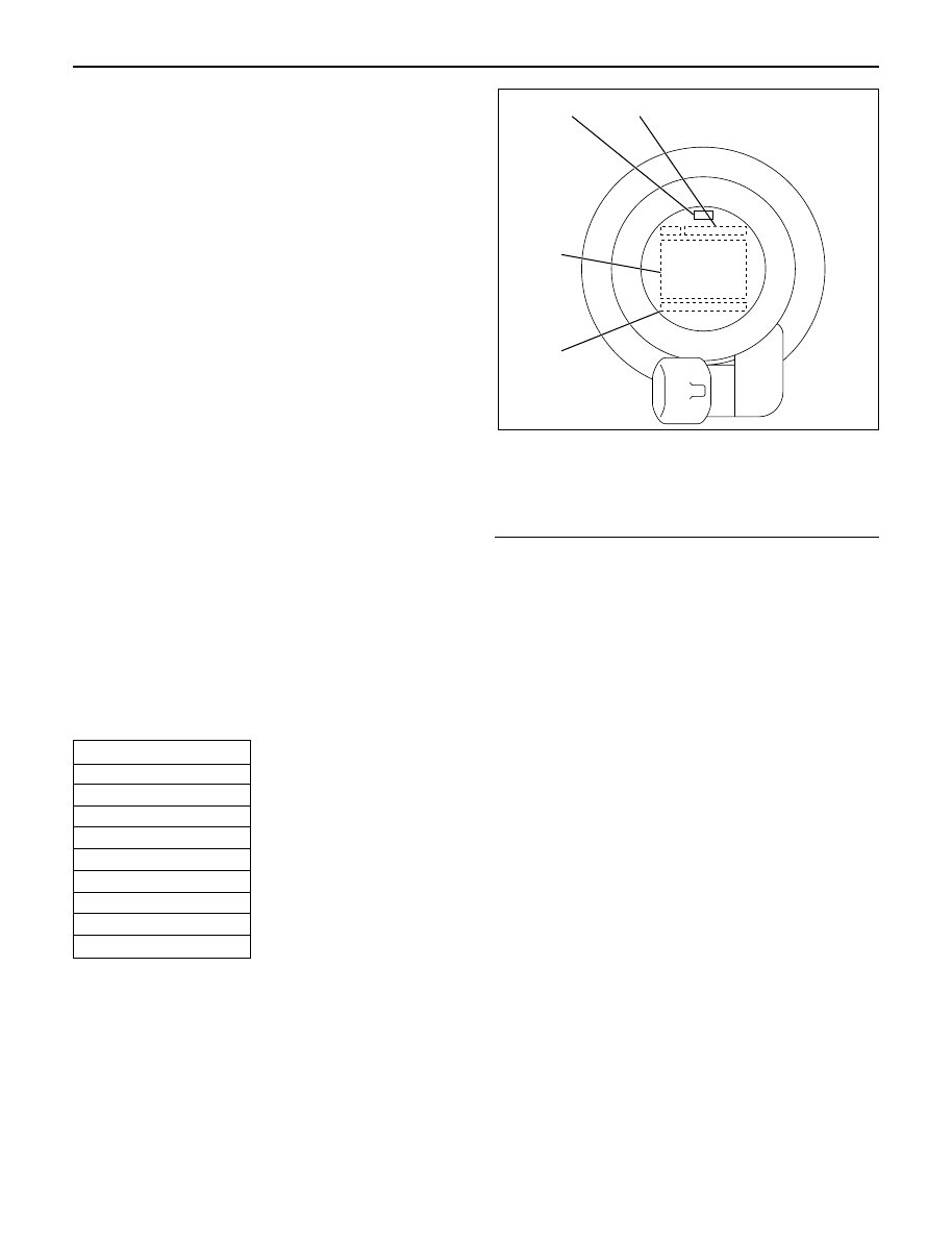
12. Record the grade code of injector for each cylinder
that is indicated on the upper portion of injector.
There are nine kinds of grade code available, one
alphabet letter and one numeral letter.
Grade code
Legend
(1) Part Number
(2) Category Number (Grade code)
(3) Serial Number
(4) Bar Code
13. Remove harness connector from each injector.
14. Loosen nuts and bolts for oil rail.
15. Remove injector fixing bolts.
16. Remove injector clamp.
17. Remove injector assembly.
INSTALLATION
1. Install oil rail, tighten temporarily
2. Install injector assembly.
NOTE:
1) Do not forget to install O-ring between injector and
oil rail.
2) Use new O-ring
3) Clean O-ring groove and fitting surface of parts.
4) Apply engine oil to O-ring.
3. Install injector fixing bolts, tighten temporarily.
4. Install injector clamp, tighten nut temporarily.
· Apply engine oil to washer both side.
5. Tighten injector fixing bolts to the specified torque.
Torque: 7 N·m (0.7 kg·m / 61 lb in)
6. Tighten injector clamp nut to the specified torque
with special method.
Torque: 30 N·m (3.1 kg·m / 22 lb ft) then loosen a
time again tighten as following torque.
Torque: 25 N·m (2.5 kg·m / 18 lb ft)
7. Tighten oil rail to the specified torque.
Torque: 20 N·m (2.0 kg·m / 14 lb ft)
1
4
3
2
055RW00001
Category number
A – 1
A – 2
A – 3
B – 1
B – 2
B – 3
C – 1
C – 2
C – 3
ENGINE FUEL 6C – 11
8. Install injector harness assembly, reconnect
harness connecter to injector.
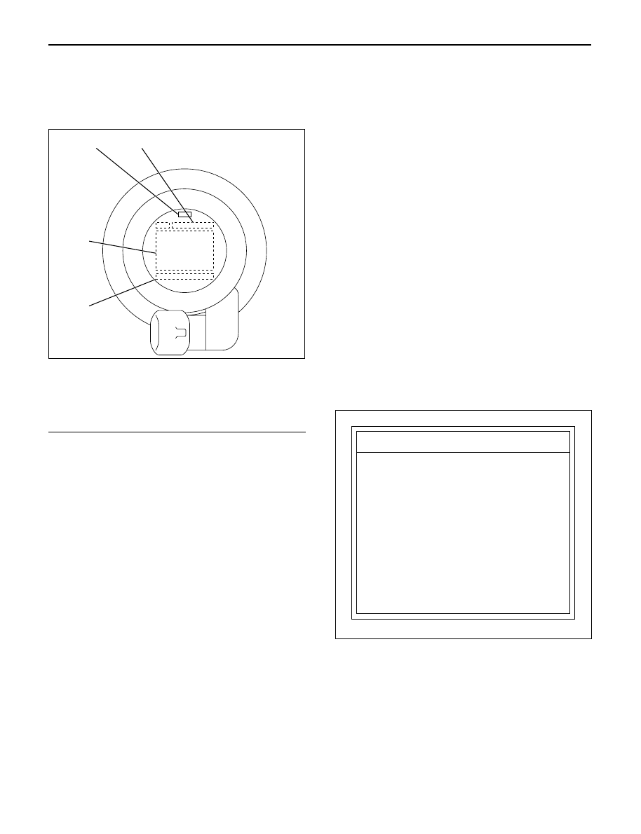
9. Record the identification marking of injector for
each cylinder that is indicated on the upper portion
of injector.
Legend
(1) Part Number
(2) Category Number (Grade code)
(3) Serial Number
(4) Bar Code
10. Install cylinder head assembly.
Refer to “Cylinder Head” in this manual.
11. Fill with about 300cc of engine oil from the high
pressure oil pipe installation port of the oil rail using
an oil filler.
If assembled without filling the oil rail with oil, the
time for engine starting will be longer.
12. Immediately install high pressure oil pipe and
tighten to specified torque.
Torque: 78 N·m (8.0 kg·m / 58 lb ft)
13. Install cylinder head noise insulator cover.
Refer to “Cylinder Head” in this manual.
14. Install intercooler assembly.
Refer to “Intercooler” in this manual.
15. Install air cleaner cover and air duct.
16. Use TECH2 to rewrite injector data to ECM.
For rewriting method refer to section “Data
Programming in Case of ECM Change” of section
6E 4JX1 engine driveability and emissions in this
manual.
NOTE:
1) On completion of servicing, bleed air from the
engine inside fuel passage by means of the priming
pump. (The priming pump should be operated more
times than in the case of conventional engines.)
2) As air is in the oil rail, it takes more time to start the
engine. Rough idling may occur while the air is
being bled completely after engine start, but it does
not indicate trouble.
The air will be bled and normal engine status will be
reached while the vehicle is driven for about 5 km
or engine is operated for about 5 minutes at 1500 to
2000 rpm.
3) The injector spare part will be provided for group
number B1, B2 and B3 only.
Injector Grade code Programming
(Injector Change)
In case of an injector change, the injector grade code
(category number) must be programmed by Tech-2.
Programming Procedure
1. Connect the Tech-2 to the vehicle DLC.
2. Turn the starter switch to the “ON” position.
3. Select the “Diagnosis” from the Main menu.
4. Select the “Programming” from the Application
menu.
1
4
3
2
055RW00001
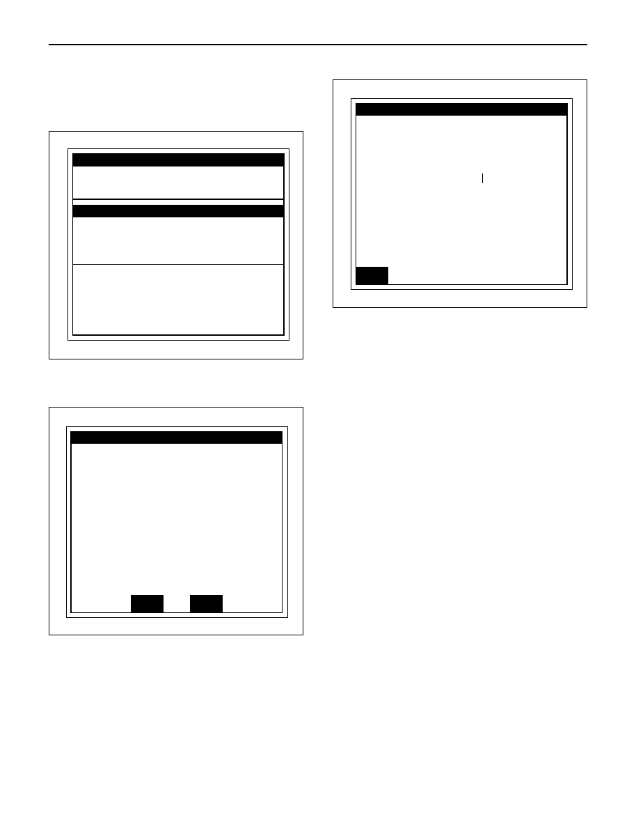
F0 :
Diagnostic Code
F1 :
Data Display
F2 :
Snapshot
F3 :
Miscellaneous Test
F4 :
Programming
Application Menu
035RW00002
6C – 12 ENGINE FUEL
5. Select “Programming Trim Date” from
Programming menu.
6. Select the injector change from Programming Trim
Date menu.
7. Select the cylinder number which changed injector.
8. Appoint and select the grade code (Category
number) of injector.
9. Confirm the completion of injector programming.
Note; The injector grade code (category number) is
indicated on the new (service part) injector.
Injector
ー
1
Injector
ー
4
Injector
ー
3
Injector
ー
1
Programming Trim Data
Select cylinder
Injector
ー
2
(W) 1998 (UE) Rodeo/Amigo,Wizard
Electronic System
3.0L L4 4JX1
035RW00003
Injector
ー
1
Programming Trim Data
Do you program trim data in
this cylinder
?
(W) 1998 (UE) Rodeo/Amigo,Wizard
Electronic System
3.0L L4 4JX1
Yes
No
035RW00004
Injectorー
1
Programming Trim Data
Programming was succeded
Category A1
(W) 1998 (UE) Rodeo/Amigo,Wizard
Electronic System
3.0L L4 4JX1
Confirmed
035RW00005
ENGINE FUEL 6C – 13
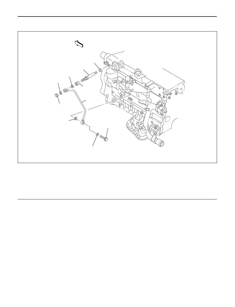
FUEL PUMP PIPE
6
2
3
10
9
8
5
4
7
1
Legend
(1)
Cap Nut
(2)
Gasket
(3)
Gasket
(4)
Pipe Nut
(5)
Adapter
(6)
Gasket
(7)
Fuel Pump Pipe
(8)
Eye Bolt
(9)
Gasket
(10)
Gasket
040R200002
REMOVAL
1. Remove eye bolt.
2. Remove cap nut.
NOTE: The eye bolt and cap nut should be
disconnected with cloth tied around them to prevent
flowing out of fuel.
3. Remove fuel pump pipe.
4. Remove pipe nut.
5. Remove adapter.
INSTALLATION
1. Apply engine oil to the thread, then install adapter
with new gasket.
Torque : 13 N·m (1.3 kg·m/113 lb in)
NOTE: Be careful not to enter the foreign material.
2. Apply engine oil to the thread, then install pipe nut.
Torque : 14 N·m (1.4 kg·m/122 lb in)
NOTE: Do not apply oil to cap nut side.
3. Install fuel pump pipe, new gaskets and cap nut to
adapter temporarily. Do not tighten the cap nut.
4. Install eye bolt with new gasket then tighten to
specified torque.
Torque : 30 N·m (3.1 kg·m/22 lb ft)
Нет комментариевНе стесняйтесь поделиться с нами вашим ценным мнением.
Текст