Opel Frontera UBS. Service manual — part 225
POWER ASSISTED BRAKE SYSTEM 5C – 45
REMOVAL
1. Master Cylinder
•
Refer to Master Cylinder Assembly in this Section.
2. Vacuum Booster
•
Refer to Vacuum Booster Assembly in this
section.
3. Yoke Clevis
4. Lock Nut
5. Retaining Clip
6. Valve Body Guard
7. Silencer
8. Filter
9. 2 gaskets and Spacer
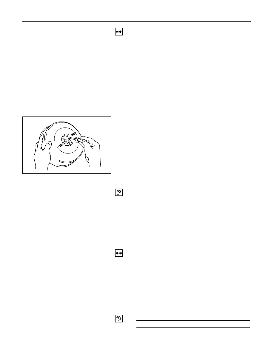
10. Retainer
•
Use a small screwdriver to pry out the retainer.
Gently pull out the plate and seal assembly from
the shell.
11. Plate and Seal Assembly
INSPECTION AND REPAIR
Visual Check:
Make necessary parts replacement if cuts, nicks,
excessive wear, or other abnormal conditions are
found through inspection. Check the following parts.
1) Yoke clevis
2) Valve body guard
3) Silencer
4) Filter
5) Plate and seal assembly
INSTALLATION
11. Plate and Seal Assembly
10. Retainer
9. 2 gaskets and Spacer
8. Filter
7. Silencer
6. Valve Body Guard
5. Retaining Clip
4. Lock Nut
Lock Nut Torque
N·m (kg·m / lb·ft)
20 (2.0 / 15)
5C – 46 POWER ASSISTED BRAKE SYSTEM
3. Yoke Clevis
2. Vacuum Booster
•
Refer to Vacuum Booster Assembly in this
section.
1. Master Cylinder
1) Refer to Master Cylinder Assembly in this Section.
2) After installation, perform brake pedal check and
adjustment. Refer to Checking Brake Pedal Height
/ Travel in this section.
POWER ASSISTED BRAKE SYSTEM 5C – 47
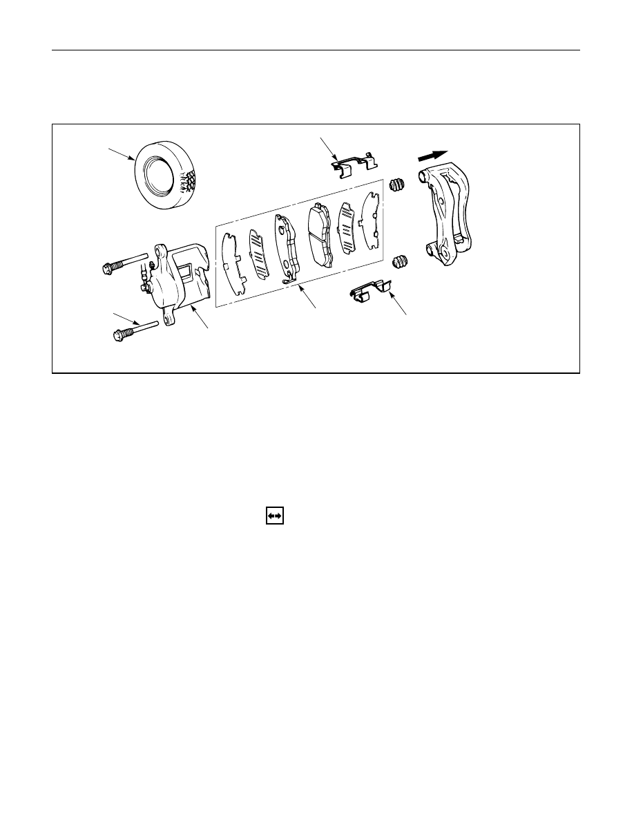
FRONT DISC BRAKE
BRAKE PADS REPLACEMENT
Outer side
1
2
3
4
5
5
Removal Steps
1.
Wheel and tire assembly
2.
Lock bolt
3.
Caliper assembly
4.
Pad assembly with shim
5.
Clip
Installation Steps
To install, follow the removal steps in the
reverse order.
REMOVAL
NOTE:
If a squealing noise occurs from the front brake while
driving, check the pad wear indicator plate. If the
indicator plate contacts the rotor, the disc pad
assembly should be replaced.
Preparation:
1) Draw out two-thirds of the brake fluid from the
reservoir.
2) Raise the vehicle and support it with suitable
safety stands.
1. Wheel and Tire Assembly
•
Refer to Wheels and Tires in Suspension section.
5C – 48 POWER ASSISTED BRAKE SYSTEM
2. Lock Bolt
3. Caliper Assembly
•
Support the caliper assembly so that the brake
hose is not stretched or damaged.
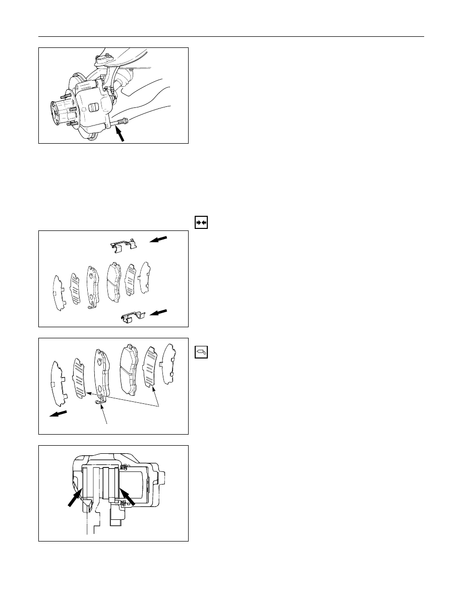
4. Pad Assembly with Shim
5. Clip
INSTALLATION
5. Clip
4. Pad Assembly with Shim
•
Apply special grease (approx 0.2 g) to both
contacting surfaces of inner shims. Wipe off
extruded grease after installing.
Inner side
Inner shim
Wear indicator
Apply
special
grease
Нет комментариевНе стесняйтесь поделиться с нами вашим ценным мнением.
Текст