Opel Frontera UBS. Service manual — part 2776
8D–304
WIRING SYSTEM
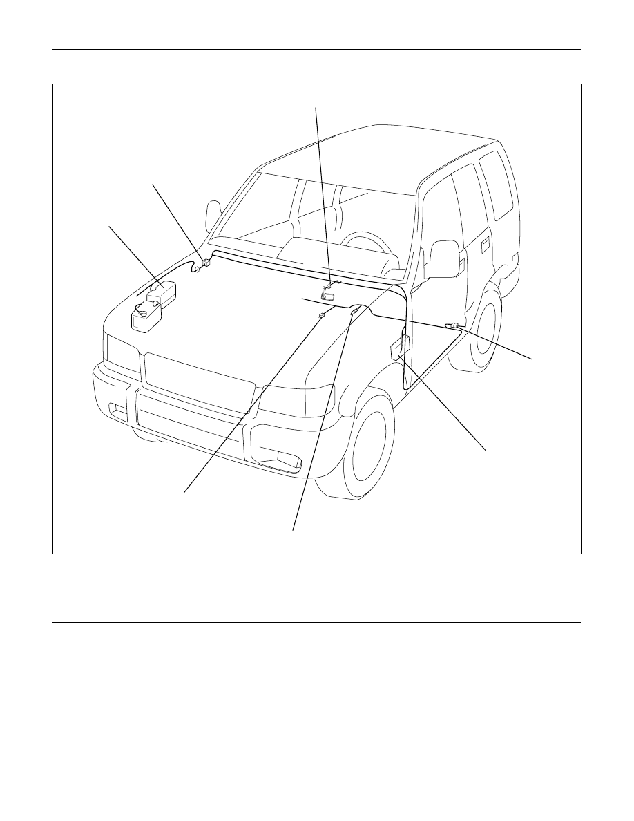
Parts Location (LHD)
4
1
7
6
2
3
5
D08RW395
Legend
(1) B-13 or B-14
(2) H-32
(3) Fuse Box
(4) B-26
(5) B-32
(6) Relay and Fuse Box
(7) H-15
WIRING SYSTEM
8D–305
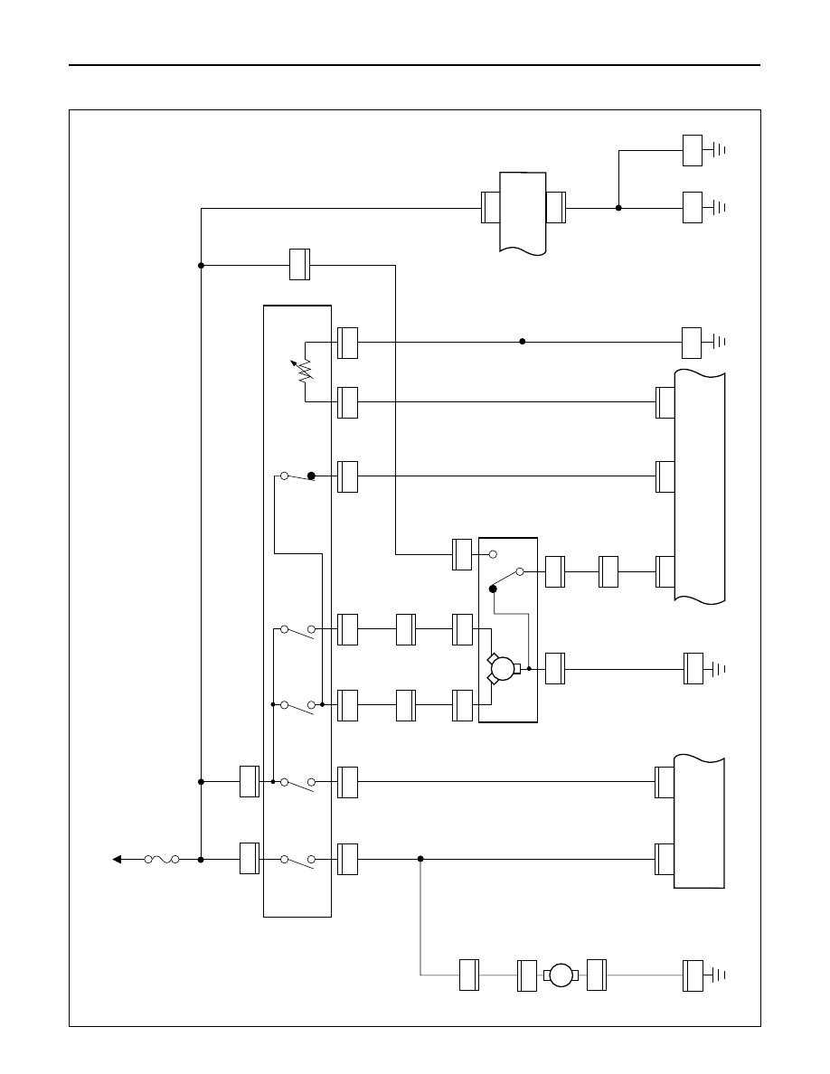
Windshield Wiper/Washer
General Description
The circuit consists of windshield wiper/washer
switch, windshield wiper motor, windshield washer
motor and alarm & relay control unit.
When windshield wiper/washer switch is turned on
with starter switch on, battery voltage is applied to
windshield wiper motor to activate wipers.
When windshield washer switch is turned on with
starter switch on, battery voltage is applied to
windshield washer motor.
Windshield washer motor squirts glass cleaning
fluid while windshield washer switch is pushed and
at the same time, alarm & relay control unit activates
windshield wiper motor to wipe glass cleaning fluid
at low speed.
8D–306
WIRING SYSTEM
Circuit Diagram (RHD)
3.0
B/R
0.85
W/L
0.85
W/L
0.85
L/Y
0.85
L/Y
0.85
L/Y
0.5
B
0.85
L/Y
C-5 15A
FRT WIPER & WASHER
STARTER SW
(IG2)
B-52
B-52
B-7
7
19
1
0.85
LG/R
B-52
B-52
B-7
2
20
0.85
O
0.85
W/L
B-52
B-7
6
11
0.85
L/R
B-52
B-6
8
14
B-7
1
0.5
B
0.85
W/L
0.85
W/L
1.25
B
0.85
B
2.0
B
2.0
B
B-52
14
B-19
3
H-13
9
0.85
R/Y
0.85
R/Y
0.85
B
B-52
5
C-38
2
H-13
C-35
C-39
4
7
C-35
2
1
M
WIND-
SHIELD
WASHER
MOTOR
WIND-
SHIELD
WIPER
MOTOR
WINDSHIELD WIPER & WASHER SW
(COMBINATION SW)
FENDER-RH
FENDER-RH
WASHER
INT
LOW
H-13
2
0.85
L
0.85
L
B-52
4
C-38
1
HIGH
OFF
M
C-39
2
C-38
3
0.85
L/O
0.85
L/O
H-13
12
B-7
12
C-38
5
B-7
9
C-38
6
ALARM & RELAY
CONTROL UNIT
BODY-LH
BODY-RH
BODY-RH
B-2
B-18
H-15
2
D08RW644
WIRING SYSTEM
8D–307
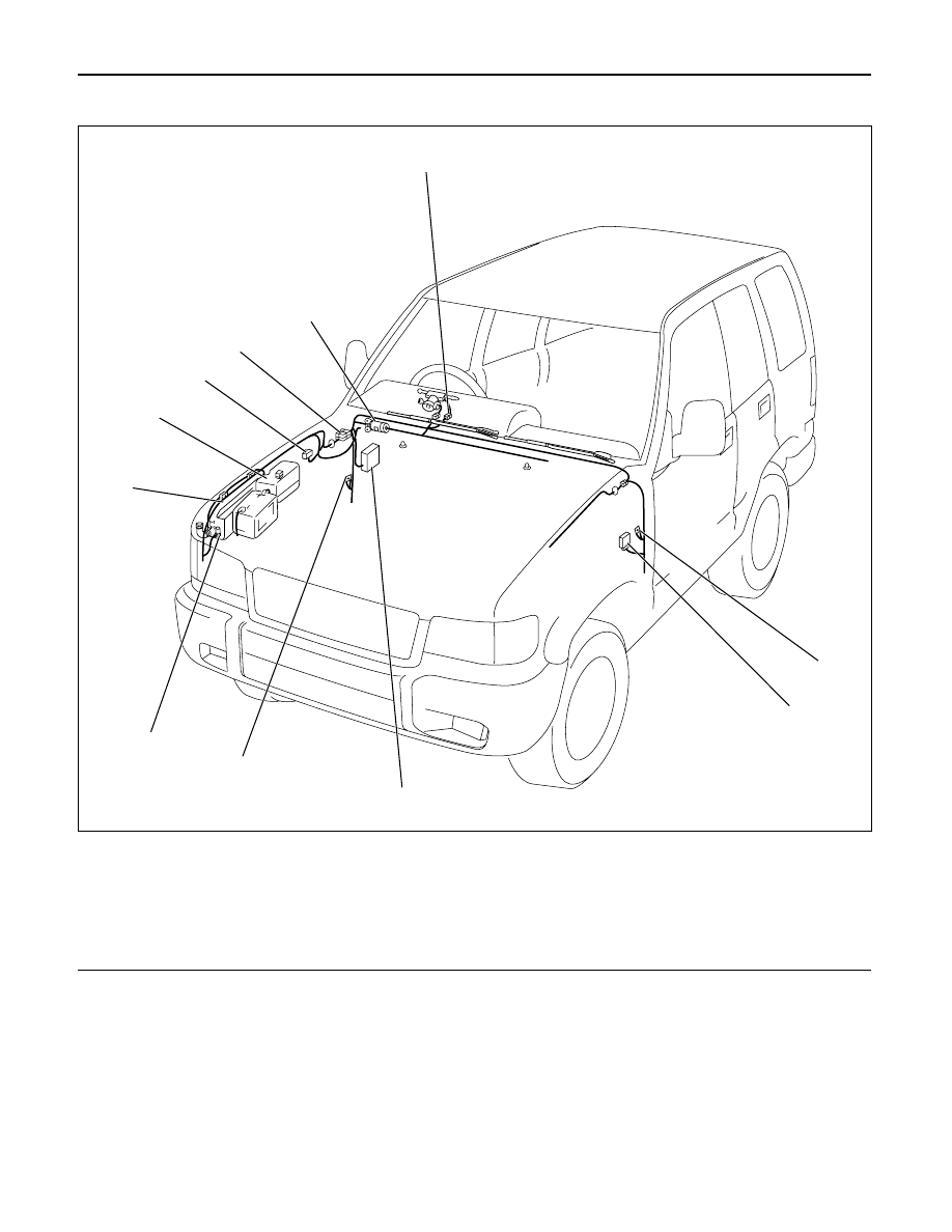
Parts Location (RHD)
Legend
(1) B-52
(2) B-2
(3) Alarm and Relay Control Unit (B-6, B-7)
(4) Fuse Box
(5) B-18, B-19
(6) FRT Wind Shild Washer Motor (C-35)
(7) Wind Shield Washer Tank
(8) Relay and Fuse Box
(9) C-39
(10) H-13, H-15
(11) Wind Shild Wiper Motor (C-38)
2
3
4
5
6
7
8
9
10
11
1
D08RWA06
Нет комментариевНе стесняйтесь поделиться с нами вашим ценным мнением.
Текст