Opel Frontera UBS. Service manual — part 635
8A–24
LIGHTING SYSTEM
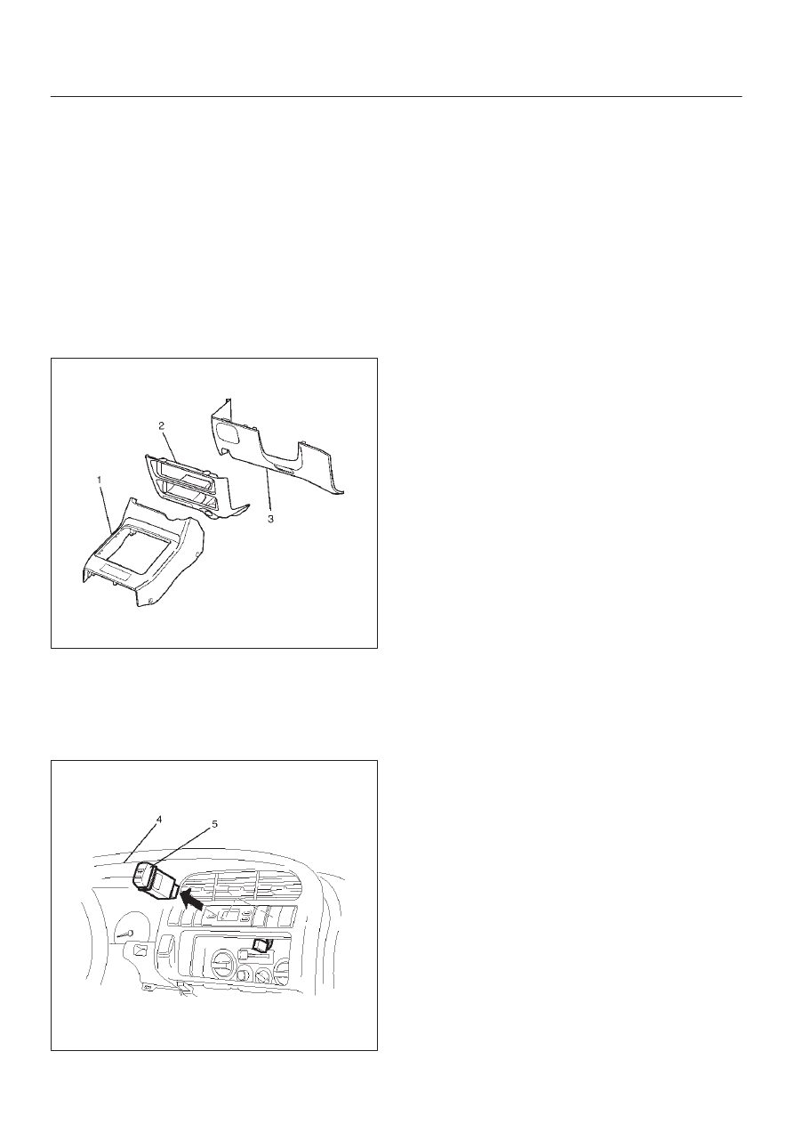
Rear Defogger Switch
Removal
1. Disconnect the battery ground cable.
2. Remove the front console assembly(1).
Refer to the Instrument Panel Assembly in Body
Structure section.
3. Remove the lower cluster assembly(2).
Refer to the Instrument Panel Assembly in Body
Structure section.
4. Remove the instrument panel driver lower cover
assembly(3).
Refer to the Instrument Panel Assembly in Body
Structure section.
821RW024
5. Remove the instrument panel cluster assembly(4).
Refer to the Instrument Panel Assembly in Body
Structure section.
6. Disconnect the connector and push the lock from the
back side of the instrument panel cluster assembly to
remove the rear defogger switch(5).
825RW023
Installation
To install, follow the removal steps in the reverse order,
noting the following point.
1. Push in the switch with your fingers until it locks
securely.
LIGHTING SYSTEM
8A–25
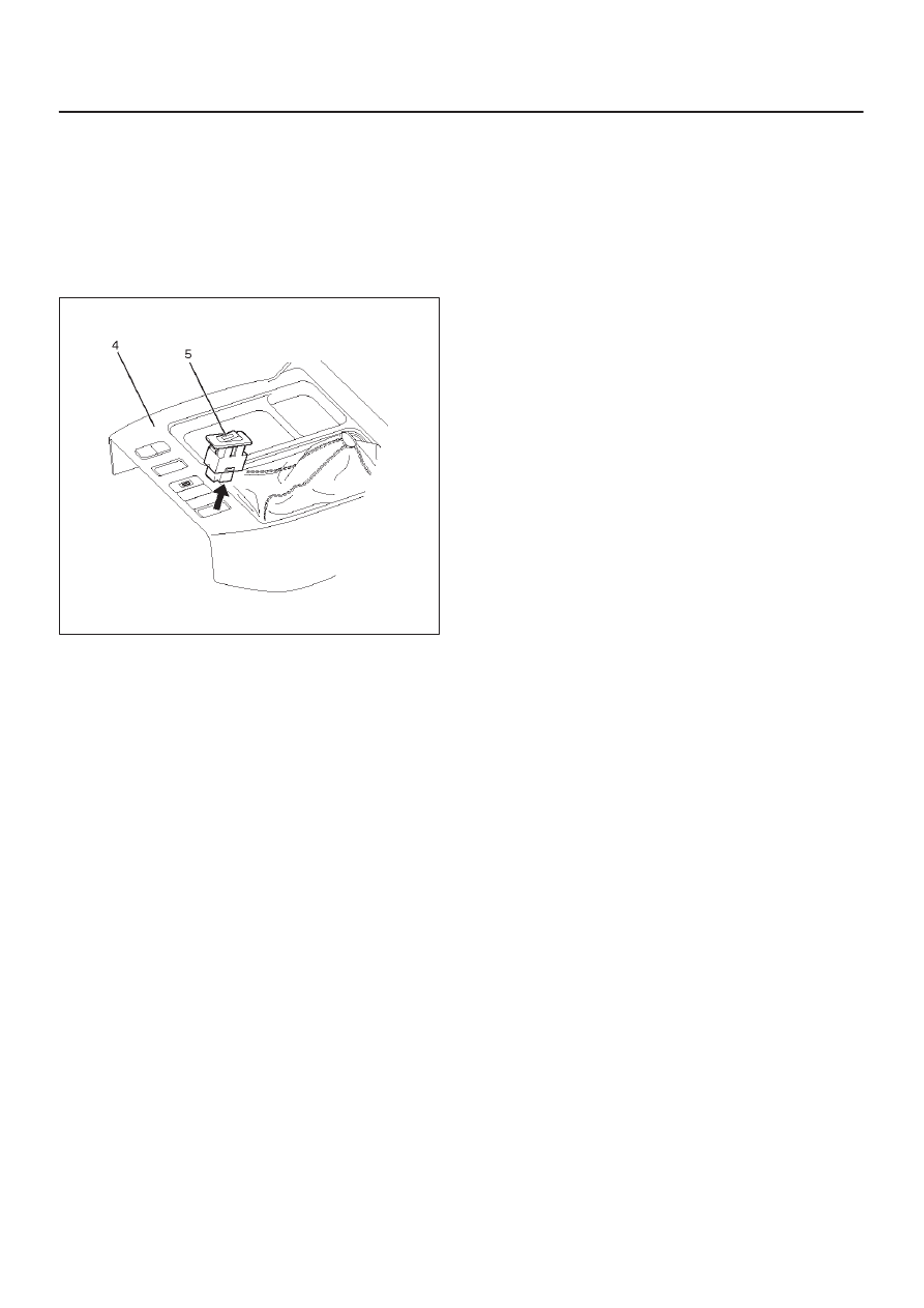
Seat Heater Switch
Removal
1. Disconnect the battery ground cable.
2. Remove four fixing screws and disconnect the switch
connectors to remove the front console assembly(4).
3. Push the lock from the back side of the front console
assembly to remove the seat heater switch(5).
825RW025
Installation
To install, follow the removal steps in the reverse order,
noting the following point.
1. Push the switch with your fingers until it locks
securely.
Key Remind Switch (Starter Switch)
Removal and Installation
Refer to the removal and installation on steps of the
Starter Switch in this section.
8A–26
LIGHTING SYSTEM
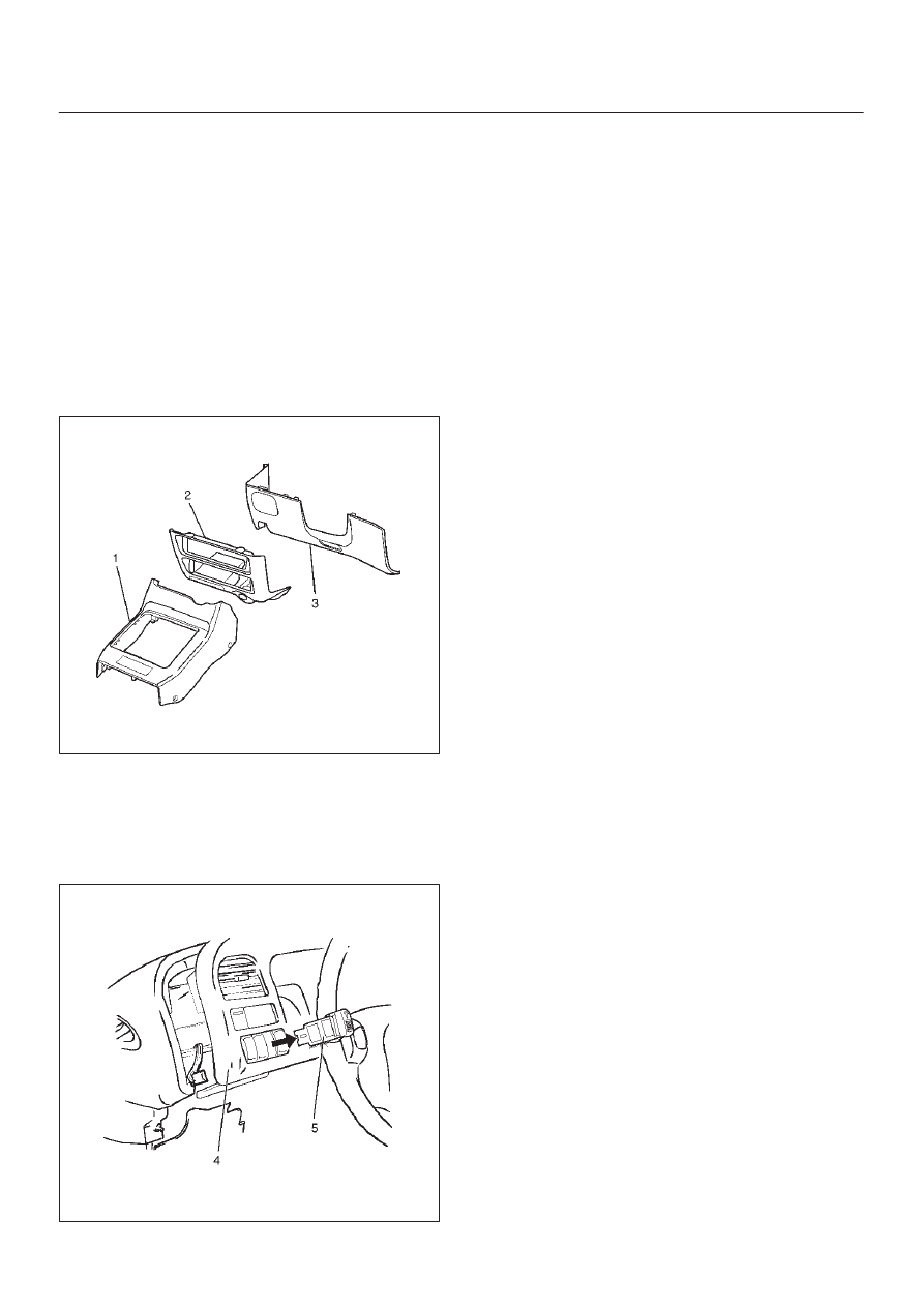
Illumination Controller
Removal
1. Disconnect the battery ground cable.
2. Remove the front console assembly(1).
Refer to the Instrument Panel Assembly in Body
Structure section.
3. Remove the lower cluster assembly(2).
Refer to the Instrument Panel Assembly in Body
Structure section.
4. Remove the instrument panel driver lower cover
assembly(3).
Refer to the Instrument Panel Assembly in Body
Structure section.
821RW024
5. Remove the instrument panel cluster assembly(4).
Refer to the Instrument Panel Assembly in Body
Structure section.
6. Disconnect the connector and push the lock from the
back side of the instrument panel cluster assembly to
remove the illumination controller(5).
825RW026
Installation
To install, follow the removal steps in the reverse order,
noting the following point.
1. Push in the switch with your fingers until the switch is
locked securely.
LIGHTING SYSTEM
8A–27
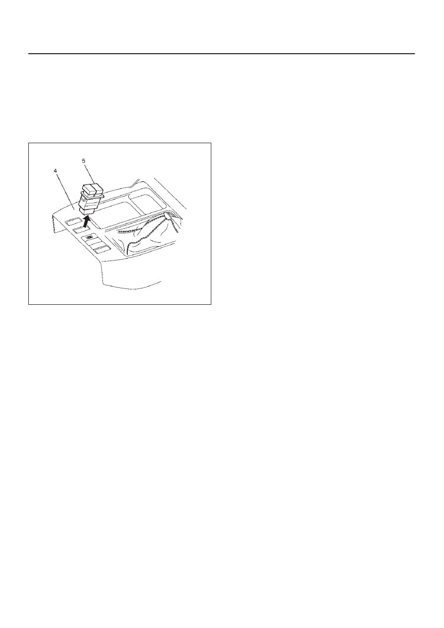
Power/Winter Switch
Removal
1. Disconnect the battery ground cable.
2. Remove four fixing screws and disconnect the switch
connectors to remove the front console assembly(4).
3. Push the lock from the back side of the front console
assembly to remove the power/winter switch(5).
825RW204
Installation
To install, follow the removal steps in the reverse order,
noting the following point.
1. Push the switch with your fingers until it locks
securely.
Нет комментариевНе стесняйтесь поделиться с нами вашим ценным мнением.
Текст