Opel Frontera UBS. Service manual — part 562

7A1–26 TRANSMISSION CONTROL SYSTEM (4L30–E)
DTC P0218 Transmission Fluid Over Temperature
Step
Action
Yes
No
1
Perform the following checks:
D
Check for possible engine system problems.
D
Transmission fluid checking procedure. Refer to Checking
Transmission Fluid Level and Condition in Automatic
Transmission (4L30–E) Section.
Were the checks performed?
Go to Step 2
—
2
1. Install the scan tool.
2. With the engine “off”, turn the ignition switch “on”.
NOTE: Before clearing DTC(s), use the scan tool to record “Failure
Records” for reference, as data will be lost when “Clear Info”
function is used.
3. Record the DTC “Failure Records”.
Is the TFT sensor signal voltage less than 0.33 volts?
Go to Step 3
Go to Diagnostic
Aids
3
1. Turn the ignition “off”.
2. Disconnect the transmission 16–way connector H–53
(additional DTCs may set).
Is the TFT sensor signal voltage greater than 4.92 volts?
Go to Internal
Wiring Harness
Check.
Go to Step 4
4
Inspect/repair circuit RED/BLK–GRN/RED for a short to ground.
Was a problem found?
Go to Step 6
Go to Step 5
5
1. Inspect the PCM for poor connections.
2. Replace the PCM if no poor connections were found.
Is the replacement complete?
Go to Step 6
—
6
1. After the repair is complete, use the scan tool to select “DTC”,
then “Clear Info” function and ensure the following conditions
are met:
TFT is less than 125
°
C (257
°
F) for at least 10 seconds.
2. Review the scan tool “DTC Info”.
Has the last test failed or is the current DTC displayed?
Begin diagnosis
again
Go to Step 1
Repair verified
Exit DTC table
TRANSMISSION CONTROL SYSTEM (4L30–E)
7A1–27
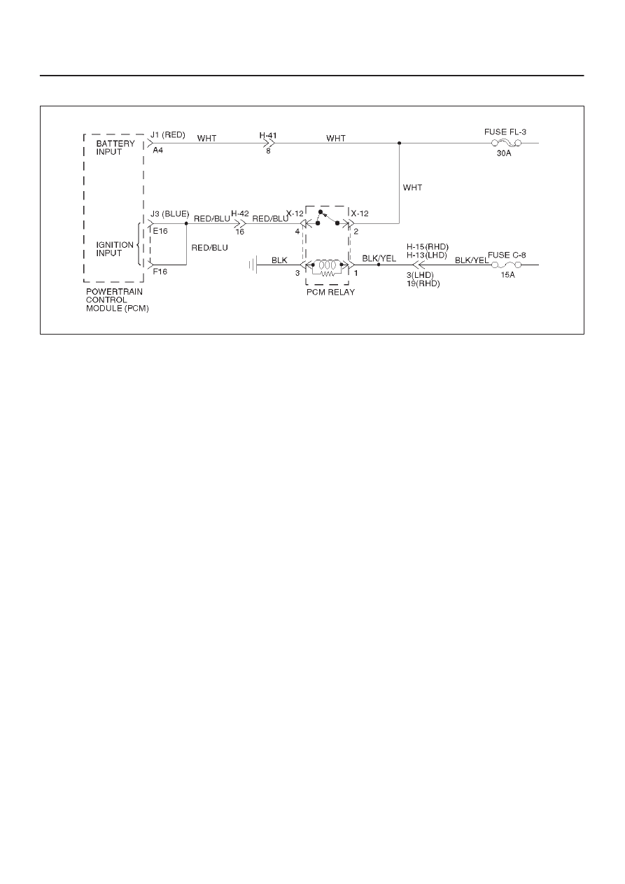
DTC P0560 System Voltage Malfunction
D07RW030
Circuit Description
Circuit WHT is the battery voltage feed for the PCM.
Circuit RED/BLU is the ignition voltage feed for the PCM.
This DTC detects a low voltage or a high voltage. This is a
type “C” DTC.
Conditions For Clearing The DTC
System Voltage Low:
D
Engine speed is greater than 1,000 rpm.
D
System voltage is less than 10 volts at a maximum
transmission temperature of 150
°
C (302
°
F).
D
System voltage is less than 7.3 volts at a minimum
transmission temperature of –40
°
C (–40
°
F).
D
All conditions met for 4 seconds.
System Voltage High:
D
System voltage is greater than 16 volts for 2 seconds.
Action Taken When The DTC Sets
D
Fixed to 4th gear.
D
Maximum line pressure.
D
Inhibit TCC engagement.
D
The PCM will illuminate the CHECK TRANS Lamp.
Conditions For Clearing The DTC
D
The DTC can be cleared from the PCM history by
using a scan tool.
D
The PCM will turn off the CHECK TRANS Lamp after
three consecutive ignition cycles without a failure
reported.
D
The DTC will be cleared from history when the vehicle
has achieved 40 warmup cycles without a failure
reported.
D
The PCM will cancel the DTC default actions when
the fault no longer exists and the ignition is cycled “off”
long enough to power down the PCM.
Diagnostic Aids
D
Charging the battery with a battery charger and jump
starting an engine may set DTC(s). If DTC(s) set
when an accessory is operated, check for faulty
connections or excessive current draw.
D
Check for faulty connections at the starter solenoid or
fusible link.
D
Check for loose/damaged terminals at generator.
D
Check belt wear/tension.
Test Description
The numbers below refer to the step numbers on the
diagnostic chart.
4. This test checks charging system voltage.
5. This test checks battery voltage input at the PCM.
7. This test checks ignition voltage input at the PCM.

7A1–28 TRANSMISSION CONTROL SYSTEM (4L30–E)
DTC P0560 System Voltage Malfunction
Step
Action
Yes
No
1
1. Install the scan tool.
2. With the engine “off”, turn the ignition switch “on”.
NOTE: Before clearing DTC(s), use the scan tool to record “Failure
Records” for reference, as data will be lost when the “Clear Info”
function is used.
3. Record the DTC “Failure Records”. Note: If any other DTCs
are present, refer to their applicable diagnostic charts before
continuing.
4. Using the J–39200 DVOM, measure the battery voltage
across the battery terminals. Record the measurement for
future reference.
Is the voltage higher than 10.5 volts?
Go to Step 2
Go to Engine
Electrical in
Engine section
2
Start the engine and warm to normal operating temperature.
Is the generator/check engine light “on”?
Go to Starting
and Charging
System in Engine
section
Go to Step 3
3
1. Increase the engine speed to 1,000–1,500 rpm.
2. Observe scan tool system voltage.
Is the system voltage within 13–15 volts.
Go to Step 4
Go to Starting
and Charging
System in Engine
section
4
1. Turn the ignition switch “off”.
2. Disconnect the J1(RED) and J3 (BLUE) PCM connector
(additional DTCs will set).
3. With the engine “off”, turn the ignition switch “on”.
4. Using the J39200 DVOM, measure the battery voltage input at
PCM connector terminals J1–A4 and J3–E16.
Is there a voltage variance between the voltage measured at the
battery (taken in Step 1) and at terminals J1–A4 and J3–E16 that
is greater than 0.5 volts?
Go to Step 5
Go to Step 6
5
Repair the high resistance condition in circuit WHT.
Was the circuit repaired?
Go to Step 10
—
6
1. Disconnect the J3 (BLUE) PCM connector.
2. Measure the ignition voltage input at PCM connector terminals
J3–E16 and J3–F16.
Is there a voltage variance between the voltage measured at the
battery (taken in Step 1) and at terminals J3–E16 and J3–F16 that
is greater than 0.5 volts?
Go to Step 7
Go to Step 8
7
Repair the high resistance condition is circuit RED/BLU.
Was the circuit repaired?
Go to Step 10
—
8
Check PCM connector terminals J1–A4, J3–E16 and J3–F16 for
bent, damaged, or backed out connector pins. Also check for
weak terminal tension.
Was a problem found?
Go to Step 10
Go to Step 9

TRANSMISSION CONTROL SYSTEM (4L30–E)
7A1–29
DTC P0560 System Voltage Malfunction (Cont’d)
Step
No
Yes
Action
9
Replace the PCM.
Is the replacement complete?
Go to Step 10
—
10
1. After the repair is complete, use the scan tool to select “DTC”,
then “Clear Info” function and operate the vehicle under the
following conditions:
Start the vehicle and warm to normal operating temperature.
The PCM must see a system voltage between 10 and 16 volts.
2. Review the scan tool “DTC Info”.
Has the last test failed or is the current DTC displayed?
Begin diagnosis
again
Go to Step 1
Repair verified
Exit DTC table
Нет комментариевНе стесняйтесь поделиться с нами вашим ценным мнением.
Текст