Opel Frontera UBS. Service manual — part 1351
6D – 24 ENGINE ELECTRICAL
1
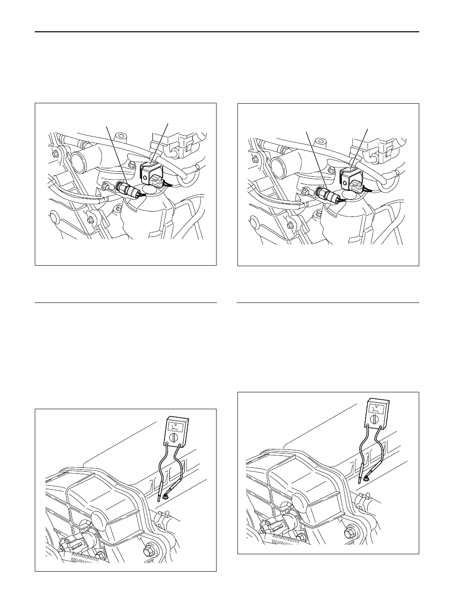
Inspection on Quick Heating Operation
1. Disconnect ECT-sensor connection on the
thermostat housing
Legend
(1) ECT Sensor
(2) EVRV
2. Connect the circuit tester between glow plug and
engine earth.
3. Inspect the following items with starter switch set to
ON position (but do not start the engine).
1) The glow indicator shall light for about 5 sec.
2) The circuit tester shall indicate power supply
voltage for 9 – 13 sec.
If above specifications are not satisfied, inspect
wire harness, glow relay and ECT-sensor. If
satisfied, inspect glow plug.
2
Inspection on Afterglow Operation
1. Disconnect ECT-sensor connection on the
thermostat housing
Legend
(1) ECT Sensor
(2) EVRV
2. Connect the circuit tester between glow plug and
engine earth.
3. Inspect the following item with the engine started.
1) The circuit tester shall indicate about 7 volts
after 360 seconds of engine start.
•
If above specifications are not satisfied, inspect
battery voltage, engine earth, wiring harness,
glow plug, and ECM.
1
2
060RW166
065RW035
1
2
060RW166
065RW035
INSPECTION ON QOS4 SYSTEM OPERATION
ENGINE ELECTRICAL 6D – 25
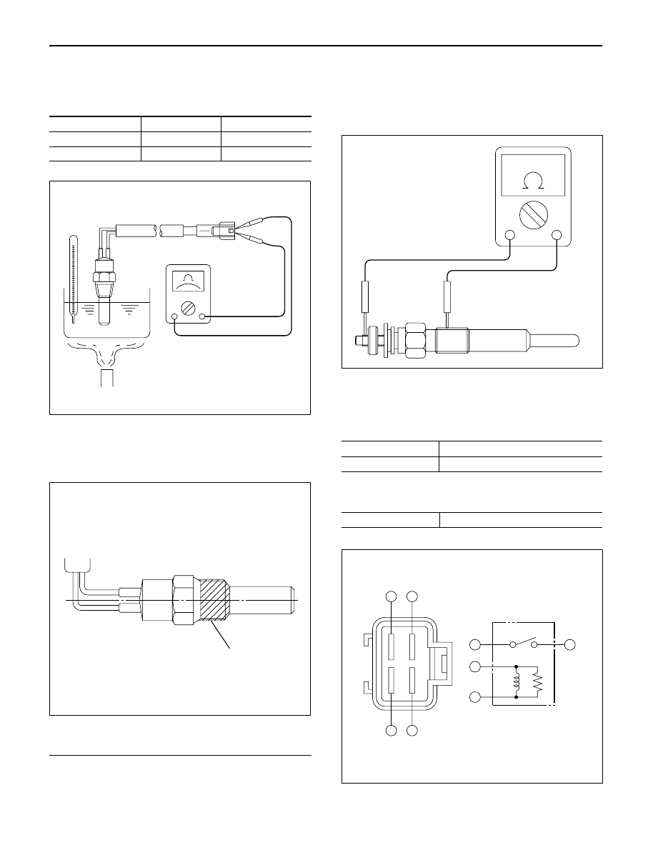
ECT SENSOR
Measure the resistance depending on the water
temperature.
Temperature (°C)
Current (mA)
Resistance (k
Ω
)
20 ± 1
1.0
2.0 – 3.0
50 ± 1
1.0
0.6 – 1.0
When installing the ECT sensor, apply sealant (Loctite
#262 or equivalent) to prevent water leakage.
Torque: 8 N·m (0.8 kg·m/69 lb in)
Legend
(1) Sealing Material
GLOW PLUG
Inspect the resistance
Resistance at normal temperature: 0.8 – 1.0
Ω
Torque: 23 N·m (2.3 kg·m/17 lb·ft)
GLOW PLUG RELAY
Inspect the continuity
(2) – (4)
No Continuity
(1) – (3)
Continuity
If battery voltage is applied to the terminal between (1)
– (3)
(2) – (4)
Continuity
065RW058
065RW061
1
065RW060
2
4
2
3
1
1
3
4
065RW037

MEMO
6E–1
4JX1–TC ENGINE DRIVEABILITY AND EMISSIONS
4JX1–TC 3.0L ENGINE
DRIVEABILITY AND EMISSIONS
CONTENTS
Specification
6E–7
. . . . . . . . . . . . . . . . . . . . . . . . . .
Tightening Specifications
6E–7
. . . . . . . . . . . . . . .
Diagrams and Schematics
6E–8
. . . . . . . . . . . . . . . .
ECM Wiring Diagram (1 of 6)
6E–8
. . . . . . . . . . . .
ECM Wiring Diagram (2 of 6)
6E–9
. . . . . . . . . . . .
ECM Wiring Diagram (3 of 6)
6E–10
. . . . . . . . . . . .
ECM Wiring Diagram (4 of 6)
6E–11
. . . . . . . . . . . .
ECM Wiring Diagram (5 of 6)
6E–12
. . . . . . . . . . . .
ECM Wiring Diagram (6 of 6)
6E–13
. . . . . . . . . . . .
ECM Pinouts
6E–14
. . . . . . . . . . . . . . . . . . . . . . . . . . .
ECM Pinout Table, 32-Way Connector – J1
RED – Upper
6E–14
. . . . . . . . . . . . . . . . . . . . . . . . .
ECM Pinout Table, 32-Way Connector – J1
RED – Lower
6E–15
. . . . . . . . . . . . . . . . . . . . . . . . .
ECM Pinout Table, 32-Way Connector – J2
BLUE – Upper
6E–16
. . . . . . . . . . . . . . . . . . . . . . . .
ECM Pinout Table, 32-Way Connector – J2
BLUE – Lower
6E–17
. . . . . . . . . . . . . . . . . . . . . . . .
ECM Pinout Table, 5-Way Connector – J3
6E–18
Component Locator
6E–19
. . . . . . . . . . . . . . . . . . . . .
Sensors and Miscellaneous Component
Locators
6E–21
. . . . . . . . . . . . . . . . . . . . . . . . . . . . .
Abbreviations Charts
6E–23
. . . . . . . . . . . . . . . . . . . .
Diagnosis
6E–24
. . . . . . . . . . . . . . . . . . . . . . . . . . . . . .
Strategy-Based Diagnostics
6E–24
. . . . . . . . . . . . .
Strategy-Based Diagnostics
6E–24
. . . . . . . . . . . . .
DTC Stored
6E–24
. . . . . . . . . . . . . . . . . . . . . . . . . . .
No DTC
6E–24
. . . . . . . . . . . . . . . . . . . . . . . . . . . . . .
No Matching Symptom
6E–24
. . . . . . . . . . . . . . . . .
Intermittents
6E–24
. . . . . . . . . . . . . . . . . . . . . . . . . .
No Trouble Found
6E–24
. . . . . . . . . . . . . . . . . . . . .
Verifying Vehicle Repair
6E–24
. . . . . . . . . . . . . . . .
General Service Information
6E–25
. . . . . . . . . . . . . .
Serviceability Issues
6E–25
. . . . . . . . . . . . . . . . . . .
Visual/Physical Engine Compartment
Inspection
6E–25
. . . . . . . . . . . . . . . . . . . . . . . . . . . .
Basic Knowledge of Tools Required
6E–25
. . . . . .
Serial Data Communications
6E–25
. . . . . . . . . . . . . .
Class II Serial Data Communications
6E–25
. . . . .
On-Board Diagnostic (OBD)
6E–25
. . . . . . . . . . . . . .
On-Board Diagnostic Tests
6E–25
. . . . . . . . . . . . .
Comprehensive Component Monitor
Diagnostic Operation
6E–25
. . . . . . . . . . . . . . . . . .
Common OBD Terms
6E–26
. . . . . . . . . . . . . . . . . .
The Diagnostic Executive
6E–26
. . . . . . . . . . . . . . .
DTC Types
6E–26
. . . . . . . . . . . . . . . . . . . . . . . . . . .
Verifying Vehicle Repair
6E–27
. . . . . . . . . . . . . . . .
Reading Flash Diagnostic Trouble Codes
6E–27
.
Reading Diagnostic Trouble Codes Using
a TECH 2
6E–28
. . . . . . . . . . . . . . . . . . . . . . . . . . . .
Tech 2 Scan Tool
6E–29
. . . . . . . . . . . . . . . . . . . . . .
Getting Started
6E–30
. . . . . . . . . . . . . . . . . . . . . . . .
DTC Modes
6E–32
. . . . . . . . . . . . . . . . . . . . . . . . . . .
DTC Information Mode
6E–32
. . . . . . . . . . . . . . . . .
Injector Test
6E–32
. . . . . . . . . . . . . . . . . . . . . . . . . .
EGR Valve Test
6E–32
. . . . . . . . . . . . . . . . . . . . . . .
Rail Pressure Control Valve Test
6E–32
. . . . . . . . .
Injector Balance Test
6E–32
. . . . . . . . . . . . . . . . . . .
Data Programming in Case of ECM Change
6E–32
Rail Pressure Sensor Programming
6E–33
. . . . . .
Injector Group Sign Programming
(Injector Change)
6E–33
. . . . . . . . . . . . . . . . . . . . .
On-Board Diagnostic (OBD) System Check
6E–35
.
Circuit Description
6E–37
. . . . . . . . . . . . . . . . . . . . .
Diagnostic Aids
6E–37
. . . . . . . . . . . . . . . . . . . . . . . .
Engine Control Module ECM Diagnosis
6E–39
. . . .
Multiple ECM Information Sensor DTCS Set
6E–39
Circuit Description
6E–39
. . . . . . . . . . . . . . . . . . . . .
Diagnostic Aids
6E–39
. . . . . . . . . . . . . . . . . . . . . . . .
EGR (Exhaust Gas Recirculation) Diagnosis
6E–41
Tech 2 Data Definitions and Ranges
6E–41
. . . . . . .
Typical Scan Data Values
6E–41
. . . . . . . . . . . . . . . .
Test Conditions
6E–41
. . . . . . . . . . . . . . . . . . . . . . . .
4JX1-TC Engine (Automatic and Manual
Transmission)
6E–42
. . . . . . . . . . . . . . . . . . . . . . . .
No Malfunction Indicator Lamp (MIL)
6E–44
. . . . . . .
Circuit Description
6E–44
. . . . . . . . . . . . . . . . . . . . .
Diagnostic Aids
6E–44
. . . . . . . . . . . . . . . . . . . . . . . .
Malfunction Indicator Lamp (MIL) “ON”
Steady
6E–47
. . . . . . . . . . . . . . . . . . . . . . . . . . . . . . . .
Circuit description
6E–47
. . . . . . . . . . . . . . . . . . . . .
Diagnostic Aids
6E–47
. . . . . . . . . . . . . . . . . . . . . . . .
Engine Cranks But Will Not Run
6E–49
. . . . . . . . . . .
Circuit Description
6E–49
. . . . . . . . . . . . . . . . . . . . .
Diagnostic Aids
6E–49
. . . . . . . . . . . . . . . . . . . . . . . .
Exhaust Gas Recirculation (EGR) System
Check
6E–52
. . . . . . . . . . . . . . . . . . . . . . . . . . . . . . . . .
Circuit Description
6E–52
. . . . . . . . . . . . . . . . . . . . .
ECM Diagnostic Trouble Codes
6E–54
. . . . . . . . . . .
ECM Diagnostic Trouble Codes
6E–54
. . . . . . . . .
Diagnostic Trouble Code (DTC) P0107
(Flash DTC 34)
MAP Sensor Circuit Low Voltage
6E–56
. . . . . . . . . .
Нет комментариевНе стесняйтесь поделиться с нами вашим ценным мнением.
Текст