Opel Frontera UBS. Service manual — part 1402
6E–202
4JX1–TC ENGINE DRIVEABILITY AND EMISSIONS
Crankshaft Position (CKP)
Sensor
Removal Procedure
1. Disconnect the negative battery cable.
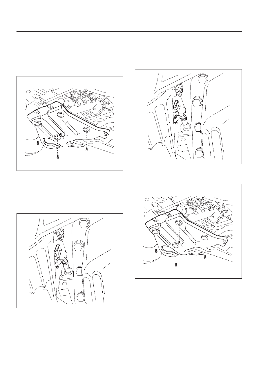
2. Remove the under cover.
035RW091
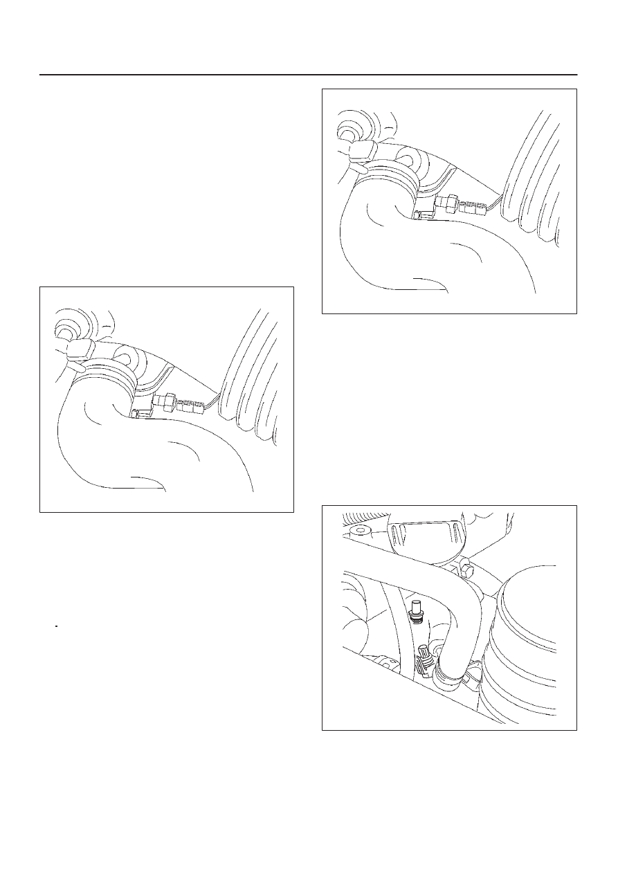
3. Disconnect the electrical connector to the CKP
sensor.
4. Remove one bolt and the CKP sensor from the left
side of the engine block.
NOTE: Use caution to avoid any hot oil that might drip
out.
035RW090
Inspection Procedure
1. Inspect the sensor O-ring for cracks or leaks.
2. Replace the O-ring if it is worn or damaged.
3. Lubricate the new O-ring with engine oil.
4. Install the lubricated O-ring.
Installation Procedure
1. Install the CKP sensor in the engine block.
2. Install the CKP sensor mounting bolt.
Tighten
D
Tighten the mounting bolt to 9 N·m (78 lb in.).
035RW090
3. Connect the electrical connector to the CKP sensor.
4. Install the under cover.
035RW091
5. Connect the negative battery cable.
6E–203
4JX1–TC ENGINE DRIVEABILITY AND EMISSIONS
Engine Coolant Temperature
(ECT) Sensor
Removal Procedure
NOTE: Care must be taken when handling the engine
coolant temperature (ECT) sensor. Damage to the ECT
sensor will affect proper operation of the fuel injection
system.
1. Disconnect the negative battery cable.
2. Drain the radiator coolant. Refer to
Draining and
Refilling Cooling System in Engine Cooling.
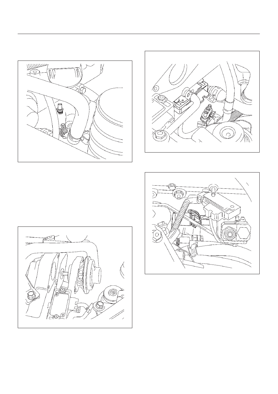
3. Disconnect the electrical connector.
4. Remove the ECT sensor from the front side of the
intake manifold.
035RW058
Installation Procedure
1. Apply sealer (LOCTITE 262) or the equivalent to the
threads of the ECT sensor.
2. Install the ECT sensor in the front side of the intake
manifold.
Tighten
D
Tighten the ECT sensor to 19 N·m (14 lb ft.).
3. Connect the electrical connector.
035RW058
4. Fill the radiator with coolant. Refer to
Draining and
Refilling Cooling System in Engine Cooling.
5. Connect the negative battery cable.
Intake Air Temperature (IAT)
Sensor
Removal Procedure
1. Disconnect the negative battery cable.
2. Disconnect the electrical connector from the IAT
sensor.
3. Remove the IAT sensor from the intake air duct by
using a rocking motion while pulling the sensor.
035RW056
6E–204
4JX1–TC ENGINE DRIVEABILITY AND EMISSIONS
Installation Procedure
1. Install the IAT sensor into the grommet in the intake
air duct.
035RW056
2. Correct the IAT electrical connector.
3. Connect the negative battery cable.
Manifold Absolute Pressure
(MAP) Sensor
Removal Procedure
1. Disconnect the negative battery cable.
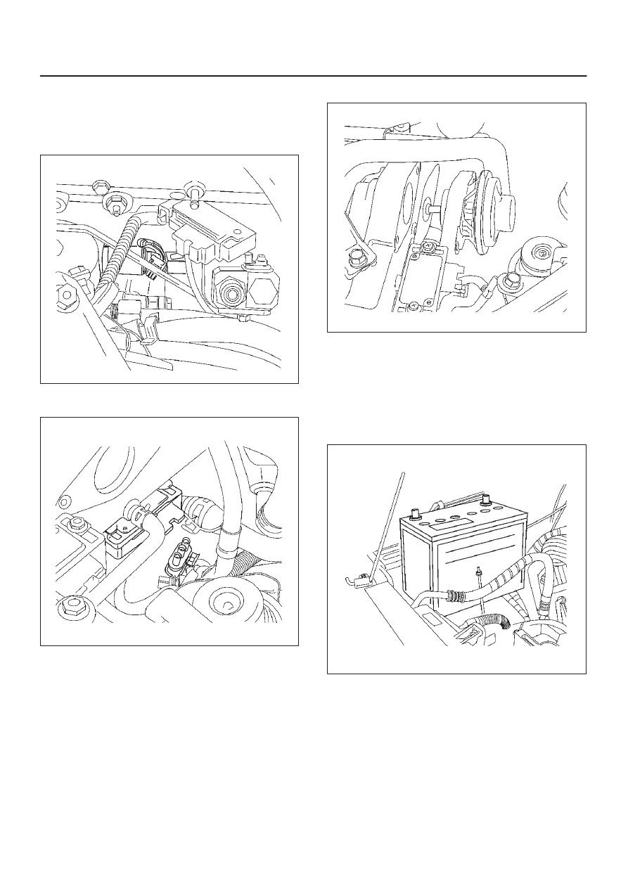
2. Disconnect the EGR valve.
035RW054
3. Disconnect the MAP sensor connector from the MAP
sensor.
035RW053
4. Remove the bolts and the MAP sensor from the
intake manifold.
035RW057
6E–205
4JX1–TC ENGINE DRIVEABILITY AND EMISSIONS
Installation Procedure
1. Install the MAP sensor and bolts on the intake
manifold.
Torque: 4 N·m (35 lb in)
035RW057
2. Connect the MAP sensor connector.
035RW053
3. Connect the EGR valve.
035RW054
4. Connect the negative battery cable.
Oil Temperature (OT) Sensor
Removal Procedure
1. Disconnect the negative battery cable.
2. Remove the battery.
035RW095
Нет комментариевНе стесняйтесь поделиться с нами вашим ценным мнением.
Текст