Opel Frontera UBS. Service manual — part 2229
6B–12
ENGINE COOLING
Drive Belt and Cooling Fan
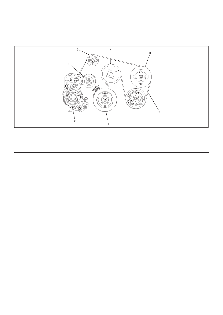
Drive Belt and Associated Parts
015RW005
Legend
(1) Crankshaft Pulley
(2) Generator
(3) Power Steering Pump
(4) Water Pump and Cooling Fan Pulley
(5) Idle Pulley
(6) Tension Pulley
(7) Drive Belt
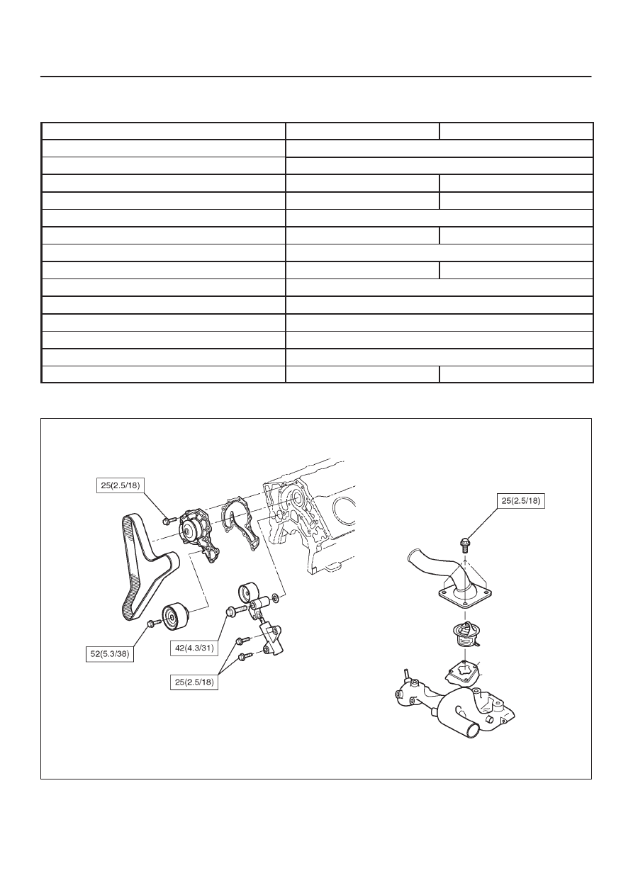
The drive belt adjustment is not required as automatic
drive belt tensioner is equipped.
Inspection
Check drive belt for wear or damage, and replace with a
new one as necessary.
Installation
Install cooling fan assembly and tighten bolts/nuts to the
specified torque.
Torque : 22 N·m (2.2 kg·m/16 lb ft) for fan pulley
and fan bracket.
Torque : 10 N·m (1.0 kg·m/87 lb in) for fan and
clutch assembly.
NOTE: Incorrect installation of a fan may cause the air for
cooling to flow in the opposite direction, this resulting in
the poor performance of the air-conditioner and a rise
temperature in engine cooling water.
ENGINE COOLING 6B–13
Main Data and Specifications
General Specifications
M/T
A/T
Cooling system
Engine coolant forced circulation
Radiator
(1 tube in row) Tube type corrugated (2 tube in row)
Heat radiation capacity
68,000 kcal/h
77,000 kcal/h
Heat radiation area
9.445m
@
(0.878ft
@
)
11.21m
@
(1.04ft
@
)
Radiator front area
0.302m
@
(0.028ft
@
)
Radiator dry weight
3.8kg (8.8lb)
4.0kg (9.9lb)
Radiator cap valve opening pressure
93.3
∼
122.7kpa (0.95
∼
1.25 kg/cm
2
, 13.5
∼
17.8psi)
Radiator coolant capacity
2.5lit (2.6U.S q.t.)
2.4lit (2.5U.S q.t.)
Engine coolant pump
Centrifugal impeller type
Delivery
300 lit (79 U.S. gal)/min or more
Pump speed
5000
±
50 rpm
Thermostat
Wax pellet type with air hole
Valve opening temperature
74.5
∼
78.5
°
C (166.1
∼
173.3
°
F)
Engine coolant total capacity
10.4lit (11.0U.S qt)
10.5lit (11.1U.S qt)
Torque Specifications
E06R200020
6B–14
ENGINE COOLING
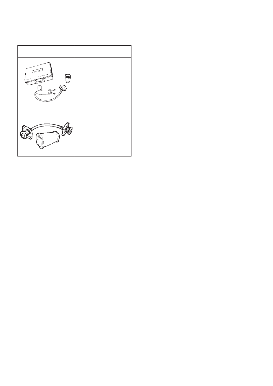
Special Tool
ILLUSTRATION
TOOL NO.
TOOL NAME
5-8840-0277-0
(J–24460–01)
Tester; radiator cap
5-8840-2603-0
(J–33984–A)
Adapter; radiator cap
6C–1
ENGINE FUEL
ENGINE
ENGINE FUEL
CONTENTS
Service Precaution
6C–1
. . . . . . . . . . . . . . . . . . . . . .
General Description
6C–2
. . . . . . . . . . . . . . . . . . . . .
Fuel Metering
6C–3
. . . . . . . . . . . . . . . . . . . . . . . . . . .
Fuel Filter
6C–4
. . . . . . . . . . . . . . . . . . . . . . . . . . . . . .
Fuel Filter and Associated Parts
6C–4
. . . . . . . . .
Removal
6C–4
. . . . . . . . . . . . . . . . . . . . . . . . . . . . .
Inspection
6C–4
. . . . . . . . . . . . . . . . . . . . . . . . . . . .
Installation
6C–5
. . . . . . . . . . . . . . . . . . . . . . . . . . . .
Inspection
6C–5
. . . . . . . . . . . . . . . . . . . . . . . . . . . .
In–Tank Fuel Filter
6C–5
. . . . . . . . . . . . . . . . . . . . .
Fuel Pump Flow Test
6C–5
. . . . . . . . . . . . . . . . . . .
Fuel Pump
6C–6
. . . . . . . . . . . . . . . . . . . . . . . . . . . . .
Fuel Pump and Associated Parts
6C–6
. . . . . . . .
Removal
6C–6
. . . . . . . . . . . . . . . . . . . . . . . . . . . . .
Installation
6C–6
. . . . . . . . . . . . . . . . . . . . . . . . . . . .
Fuel Pump Relay
6C–7
. . . . . . . . . . . . . . . . . . . . . . . .
General Description
6C–7
. . . . . . . . . . . . . . . . . . . . .
Fuel Tank
6C–7
. . . . . . . . . . . . . . . . . . . . . . . . . . . . . .
Fuel Tank and Associated Parts
6C–7
. . . . . . . . .
Removal
6C–7
. . . . . . . . . . . . . . . . . . . . . . . . . . . . .
Installation
6C–8
. . . . . . . . . . . . . . . . . . . . . . . . . . . .
Fuel Tube / Quick – Connect Fittings
6C–8
. . . . . . .
Precautions
6C–8
. . . . . . . . . . . . . . . . . . . . . . . . . . .
Cautions During Work
6C–8
. . . . . . . . . . . . . . . . . .
Removal
6C–8
. . . . . . . . . . . . . . . . . . . . . . . . . . . . .
Reuse of Quick–Connector
6C–10
. . . . . . . . . . . . . . .
Assembling Advice
6C–10
. . . . . . . . . . . . . . . . . . . . . .
Fuel Gauge Unit
6C–11
. . . . . . . . . . . . . . . . . . . . . . . .
Fuel Gauge Unit and Associated Parts
6C–11
. . .
Removal
6C–11
. . . . . . . . . . . . . . . . . . . . . . . . . . . . .
Installation
6C–11
. . . . . . . . . . . . . . . . . . . . . . . . . . . .
Fuel Filler Cap
6C–12
. . . . . . . . . . . . . . . . . . . . . . . . . .
General Description
6C–12
. . . . . . . . . . . . . . . . . . . . .
Inspection
6C–12
. . . . . . . . . . . . . . . . . . . . . . . . . . . .
Main Data and Specifications
6C–13
. . . . . . . . . . . . .
Service Precaution
WARNING: THIS VEHICLE HAS A SUPPLEMENTAL
RESTRAINT SYSTEM (SRS). REFER TO THE SRS
COMPONENT AND WIRING LOCATION VIEW IN
ORDER TO DETERMINE WHETHER YOU ARE
PERFORMING SERVICE ON OR NEAR THE SRS
COMPONENTS OR THE SRS WIRING. WHEN YOU
ARE PERFORMING SERVICE ON OR NEAR THE SRS
COMPONENTS OR THE SRS WIRING, REFER TO
THE SRS SERVICE INFORMATION. FAILURE TO
FOLLOW WARNINGS COULD RESULT IN POSSIBLE
AIR BAG DEPLOYMENT, PERSONAL INJURY, OR
OTHERWISE UNNEEDED SRS SYSTEM REPAIRS.
CAUTION: Always use the correct fastener in the
proper location. When you replace a fastener, use
ONLY the exact part number for that application.
ISUZU will call out those fasteners that require a
replacement after removal. ISUZU will also call out
the fasteners that require thread lockers or thread
sealant. UNLESS OTHERWISE SPECIFIED, do not
use supplemental coatings (Paints, greases, or other
corrosion inhibitors) on threaded fasteners or
fastener joint interfaces. Generally, such coatings
adversely affect the fastener torque and the joint
clamping force, and may damage the fastener. When
you install fasteners, use the correct tightening
sequence and specifications. Following these
instructions can help you avoid damage to parts and
systems.
Нет комментариевНе стесняйтесь поделиться с нами вашим ценным мнением.
Текст