Opel Frontera UBS. Service manual — part 1074
4D2–12 TRANSFER CASE (TOD)
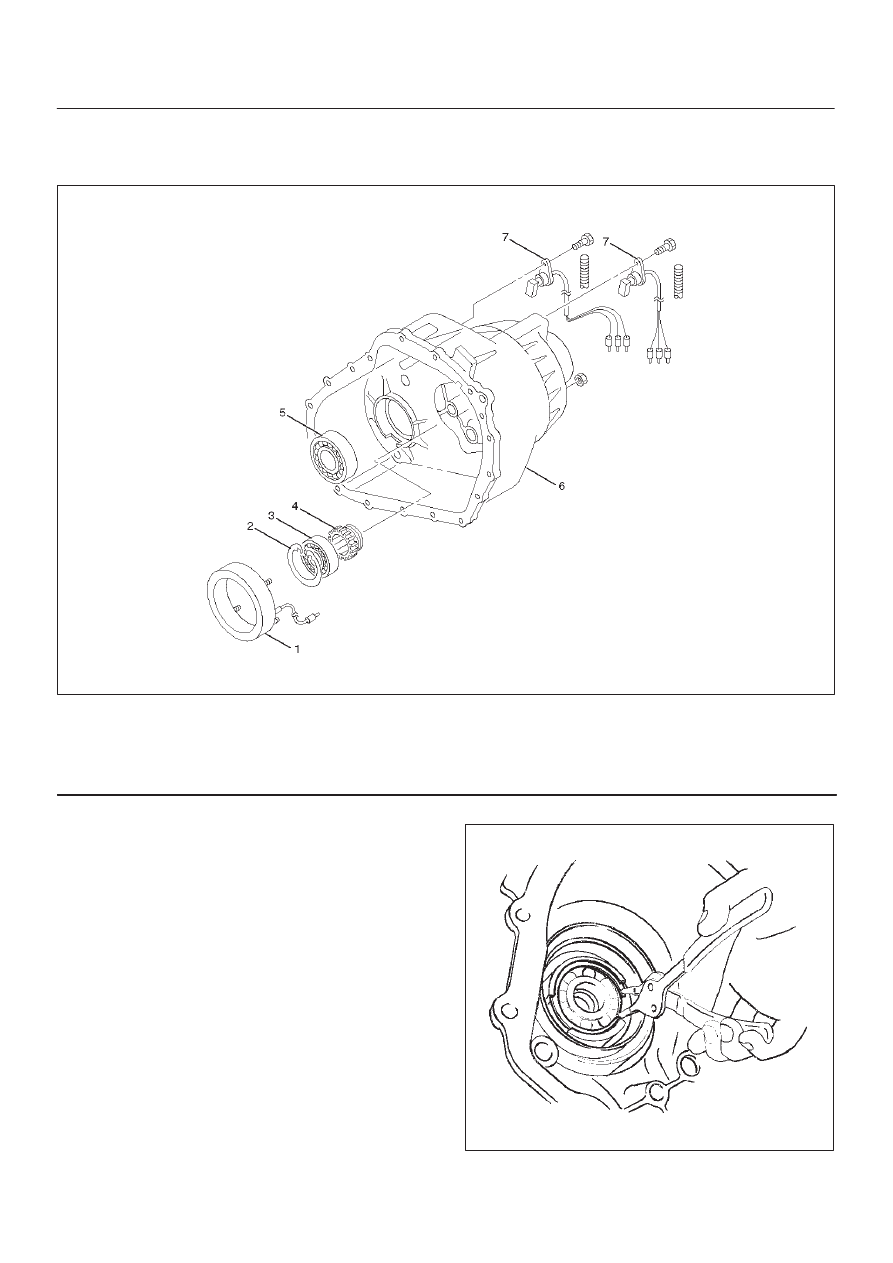
Transfer Cover Assembly
Disassembled View
261RW007
Legend
(1) Coil Assembly
(2) Snap Ring
(3) Ball Bearing
(4) Speed Gear and Tone Wheel
(5) Ball Bearing
(6) Transfer Cover Assembly
(7) Front and Rear Speed Sensors
Disassembly
1. Using snap ring pliers, remove the snap ring.
261RW047
4D2–13
TRANSFER CASE (TOD)
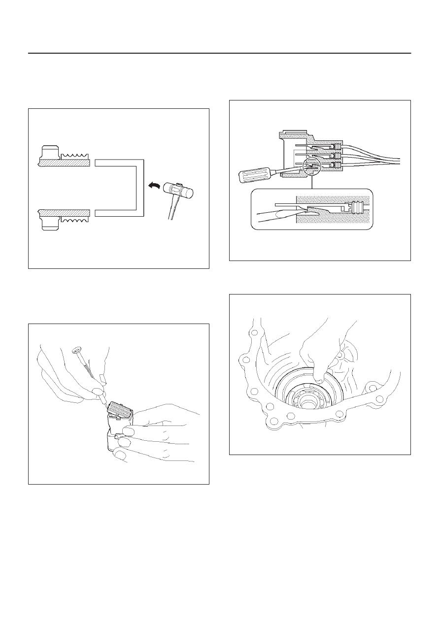
2. Strike the speed gear and tone wheel with a rod or
other appropriate tool from the outside of the transfer
cover assembly, and remove the ball bearing and
speed gear and tone wheel.
NOTE: Be careful not to damage the speed gear teeth.
266RW018
3. Remove the stopper plate on the back with a
precision screwdriver or other appropriate tool
starting from the small lock of the plate.
NOTE: Be careful not to damage the stopper plate during
the work.
261RW042
4. Using a terminal pull-out tool or an equivalent tool,
push down the lock to unlatch the terminal for the coil
assembly, and pull the terminal out.
NOTE: Be careful not to damage other terminals.
261RW032
5. Remove the fixing nuts of the coil assembly from the
outside of the transfer cover assembly. Remove the
coil assembly from the transfer cover.
261RW030
4D2–14 TRANSFER CASE (TOD)
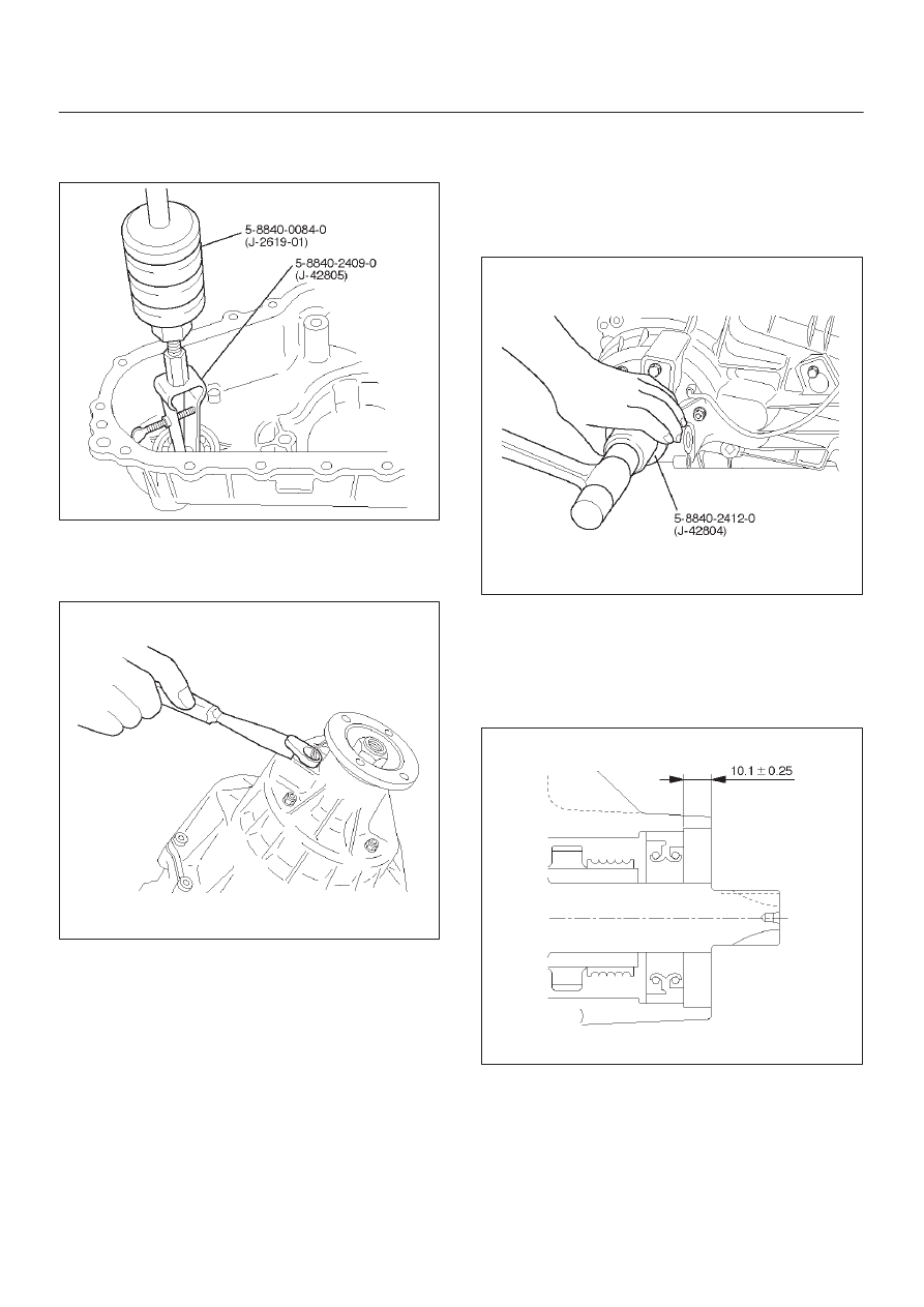
6. Using the bearing remover 5-8840-2409-0 (J-42805)
and slide hammer 5-8840-0084-0 (J-2619-01),
remove the ball bearing for the front output shaft.
901RW234
7. Remove the bolts and front and rear speed sensors.
NOTE: Be careful not to damage the speed sensors
during the work.
261RW033
Reassembly
1. Remove the oil seal from the transfer cover assembly.
2. Apply oil to the circumference of the new oil seal and
fill the lip with grease (Besco L2 or equivalent).
3. Using the oil seal installer 5-8840-2412-0 (J-42804),
install the oil seal to the transfer cover assembly.
261RW051
Rear Output Shaft Oil Seal
Distance between the transfer case end and oil seal.
NOTE: When installing the oil seal to the specified
dimension, be careful not to damage it.
Dimension : 9.85 — 10.35mm (0.39 — 0.41 in)
A04RW004
4D2–15
TRANSFER CASE (TOD)
4. Apply a thin coat of grease to the seal ring of each
front and rear speed sensor, and mount the sensors
carefully.
5. Tighten the bolts to the specified torque.
Torque : 5 N·m (0.5 kg·m/43 lb in)
NOTE: Pay attention not to mount the front (or rear)
sensor to the rear (or front) sensor position.
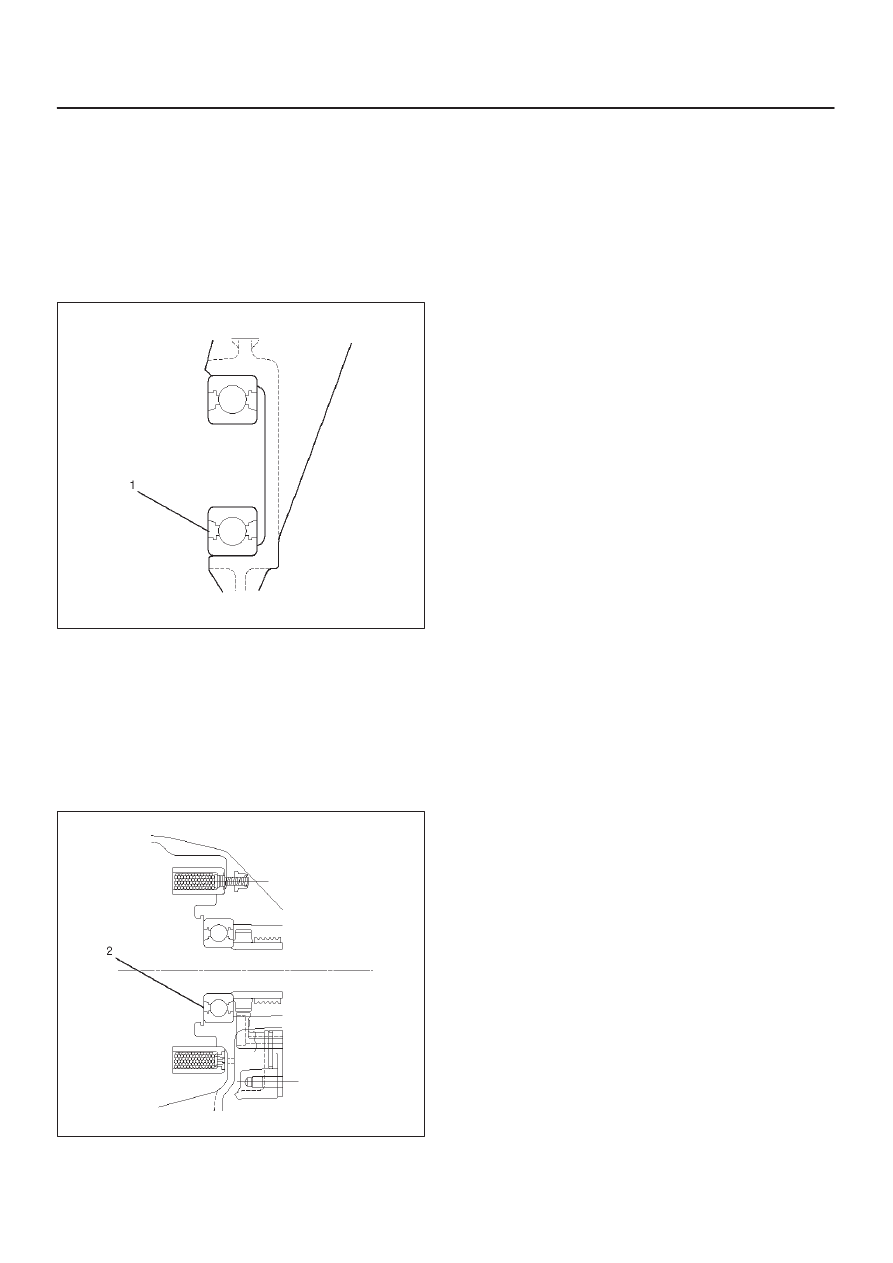
6. Install the ball bearing (1) for the front output shaft as
flat as shown in the figure.
261RW008
7. Mount the coil assembly and tighten the nuts to the
specified torque.
Torque : 10 N·m (1.0 kg·m/87 lb in)
8. Connect the terminal in the central connector.
NOTE: Be careful not to damage other terminals.
9. Install speed gear and tone wheel.
10. Mount the ball bearing (2) as flat as shown in the
figure.
261RW009–1
11. Using snap ring pliers, install the snap ring to the
transfer cover assembly.
NOTE: Securely install the snap ring to the groove of the
transfer cover assembly.
Нет комментариевНе стесняйтесь поделиться с нами вашим ценным мнением.
Текст