Opel Frontera UBS. Service manual — part 2350
6E–436
6VE1 3.5 ENGINE DRIVEABILITY AND EMISSIONS
Diagnostic Trouble Code (DTC) P1574 Brake Switch No Operation
D06R200076
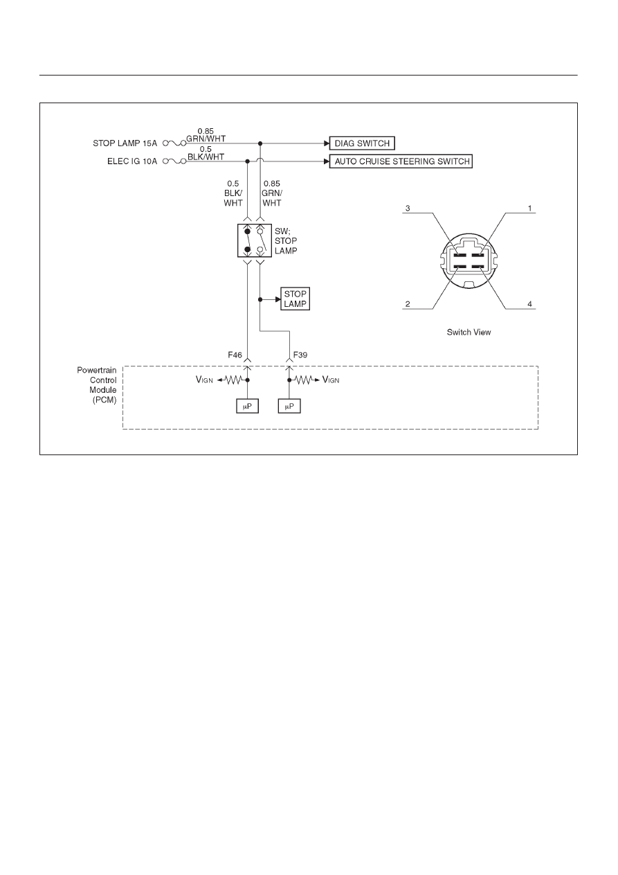
Circuit Description
The brake switch has 3 functions.
D
Brake pedal operation check
D
Brake light operation (On and off)
D
Cruise control (Cancel)
The PCM receives vehicle speed and switch position
signals from the brake switch. The PCM sets brake
operating conditions in response to these signals.
If the brake switch is on, the brake system is in normal
operation (cruise control cancelled).
Conditions for Setting the DTC
D
Two break switch signals do not acknowledge after
signal changed.
D
Switch does not change during accelerating vehicle or
decelerating.
D
VSS is not fault.
D
Engine is running.
Action Taken When the DTC Sets
D
The PCM will not turn the malfunction indicator lamp
(MIL) “ON”.
D
The PCM will store conditions which were present
when the DTC was set as Failure Records only. This
information will not be stored as Freeze Frame data.
Conditions for Clearing the DTC
D
DTC P1574 can be cleared by using the scan tool
“Clear Info” function or by disconnecting the PCM
battery feed.
Diagnostic Aids
D
Damaged harness–Inspect the wiring harness for
damage. If the harness appears to be OK, observe the
fuel level display on the scan tool while moving
connectors and wiring harnesses related to the sensor.
A change in the display will indicate the location of the
fault.

6E–437
6VE1 3.5L ENGINE DRIVEABILITY AND EMISSIONS
DTC P1574 Brake Switch No Operation
Step
Action
Value(s)
Yes
No
1
Was the “On-Board Diagnostic (OBD) System Check”
performed?
—
Go to
Step 2
Go to
OBD
System
Check
2
1. Ignition “Off”. Engine “Off”.
2. Check following fuses.
D
BACK 15A
D
STOP LAMP 15A
3. If a problem found repair as necessary.
Was a problem found?
—
Verify repair
Go to
Step 3
3
1. Make adjustment to the brake switch.
(Refer to
“Brake switch” in “10A CRUISE
CONTROL SYSTEM”.)
2. If a problem found repair as necessary.
Was the problem found?
—
Verify repair
Go to
Step 4
4
1. Push the shaft on brake switch.
2. Check shaft operation for smooth movement.
3. If a problem found repair as necessary.
Was the problem found?
—
Verify repair
Go to
Step 5
5
1. Disconnect the connector at brake switch.
2. Check following terminal pin by ohmmeter.
(Leave the shaft position at brake switch. Don’t
push it.)
D
Between pin 1 and pin 2
D
Between pin 3 and pin 4
Was it specified value?
Between pin1
and pin2 is
0
W
, Between
pin3 and pin4
is
∞
W
Go to
Step 6
Go to
Step 9
6
1. Disconnect the connector at brake switch.
2. Check following terminal pin at ohmmeter.
(Don’t press the button of the brake switch.)
D
Between pin 1 and pin 2
D
Between pin 3 and pin 4
Was it specified value?
Between pin1
and pin2 is
∞
W
, Between
pin3 and pin4
is 0
W
Go to
Step 7
Go to
Step 9
7
1. Probe related circuits for open or short to ground.
2. If a problem was found, repair as necessary.
Was a problem found?
—
Verify repair
Go to
Step 8
8
1. Replace the PCM.
IMPORTANT: The replacement PCM must be
programmed. Refer to
On-Vehicle Service in
Powertrain Control Module and Sensors for
procedures.
And also refer to latest Service Bulletin.
Check to see if the Latest software is released or not.
And then Down Load the LATEST PROGRAMMED
SOFTWARE to the replacement PCM.
Was the action completed?
—
Verify repair
—
9
1. Replace the brake switch.
Was the action completed?
—
Verify repair
—
6E–438
6VE1 3.5 ENGINE DRIVEABILITY AND EMISSIONS
Diagnostic Trouble Code (DTC)
P1626 No response from immobilizer
D06R200118
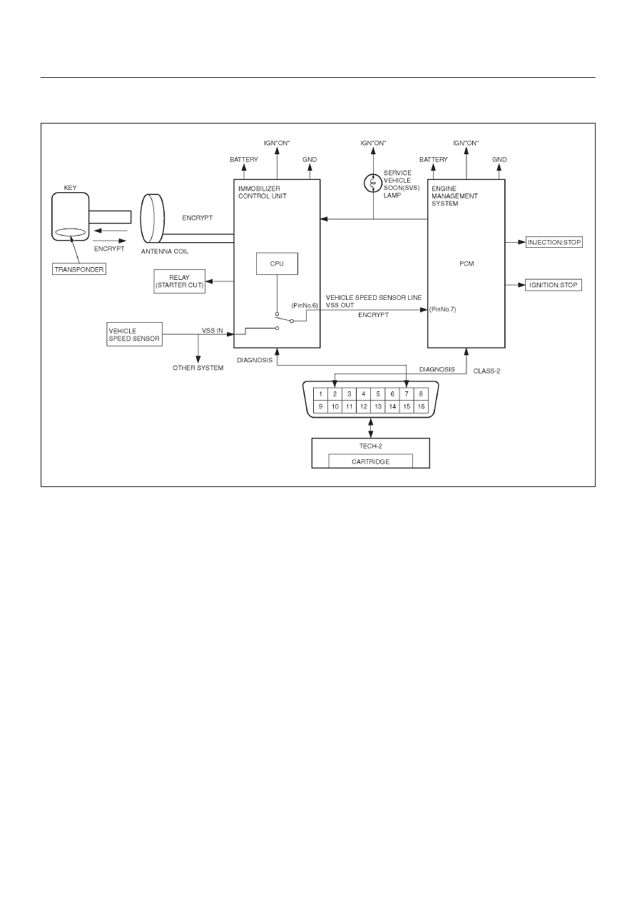
Circuit Description
The PCM decides whether that is an abnomality in the
immobilizer control system. DTC P1626 or are recorded
by the PCM when no response from immobilizer.
Condition for Setting the DTC
D
No response from immobizer.
Action Taken When the DTC sets
D
Flashing the SVS lamp
D
The Engine does not start.
Condition for Clearing the MIL/DTC
D
Use clear DTC information with Tech 2. (Refer to
the
immobilizer workshop manual.) (ISUZU UES
Immobilizer system)
Diagnostic Aids
Check for the following conditions:
D
Poor connection at PCM and ImmobilizerInspect
harness connectors for backed out terminals, improper
mating, broken locks, improperly formed or damaged
terminals, and poor terminal to wire connection.
D
Damaged harness-Inspect the wiring harness for
damage, If the harness appears to be OK, disconnect
the PCM and Immobilizer, turn the ignition “ON” and
observe a voltmeter connected to the suspect driver
circuit at the PCM and Immobilizer harnass connector
while moving connectors and wiring harnesses relates
to the SVS lamp.
A change in voltage will indicate the location of the
fault.

6E–439
6VE1 3.5L ENGINE DRIVEABILITY AND EMISSIONS
DTC P1626-No response from immobilizer
Step
Action
Value(s)
Yes
No
1
Was the “On-Board Diagnostic (OBD) system Check”
performed?
—
Go to
Step 2
Go to
OBD
system check
2
Using the Tech 2 system selection menu, select Body
function.
Does the Tech 2 display B**** appear?
—
Refer to
“Immobilizer
workshop
manual”
Go to
Step 3
3
Does the Tech 2 display DTC P1626 appear?
—
Go to
Step 4
Refer to
Diagnostic
Aids
4
1. Check the Circuit for Immobilizer system.
2. Disconnect the VEHICLE SPEED SENSOR LINE
VSS OUT harness.
3. Check the circuit open or short voltage between the
Pin No.7 and Pin No.6 by DMM.
If a problem found, repair as necessary.
Was a problem found?
—
Verify repair
Go to
Step 5
5
Replace the PCM.
IMPORTANT: The replacement PCM must be
programmed. Refer to
On-Vehicle Service in
Powertrain Control Module and Sensors for
procedures, and immobilizer system workshop
manual.
And also refer to latest Service Bulletin.
Check to see if the Latest software is released or not.
And then Down Load the LATEST PROGRAMMED
SOFTWARE to the replacement PCM.
Is the action complete?
—
Verify repair
—
Нет комментариевНе стесняйтесь поделиться с нами вашим ценным мнением.
Текст