Opel Frontera UBS. Service manual — part 1522
7B–42 MANUAL TRANSMISSION
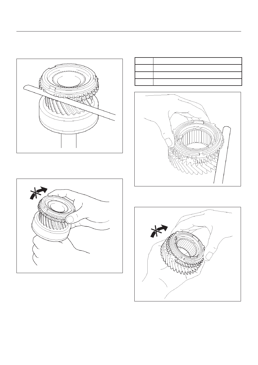
5. Using a thickness gauge, measure the clearance
between the 4th block ring back and gear spline
end.
Standard: 0.75 – 1.65 mm (0.030 – 0.065 in)
226RW064
6. Check the braking effect of the block ring. Turn
the block ring in one direction while pushing it to
the gear cone. Check that the ring locks. If it does
not lock, replace the block ring.
226RW060
7. Install the needle roller bearing.
2. Reassemble the mainshaft assembly.
NOTE: Apply all parts with engine oil before installing
them.
3. Inspect block ring
1. Using a thickness gauge, measure the clearance
between the synchronizer ring back and gear
spline end.
Gear
Standard Clearanse
1st
0.80 – 1.60 mm (0.032 – 0.063 in)
2nd
0.65 – 1.75 mm (0.026 – 0.069 in)
3rd
0.75 – 1.65 mm (0.030 – 0.065 in)
226RW105
2. Turn the synchronizer ring in one direction while
pushing it to the gear cone. Check that the ring
locks.
226RW106
MANUAL TRANSMISSION
7B–43
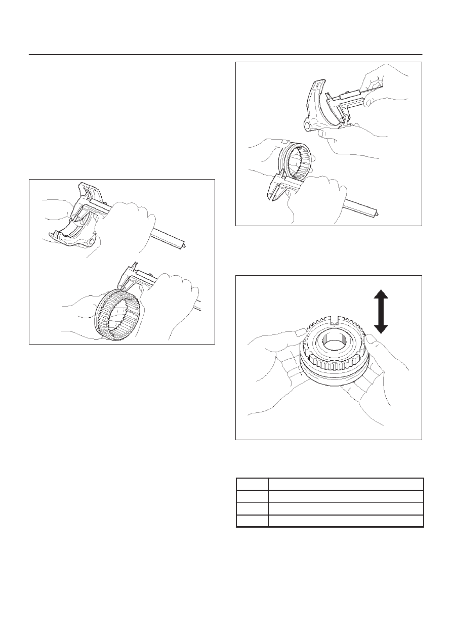
4. Inspect hub sleeve and shift arm.
1st–2nd shift arm
1. Using a vernier caliper, measure center groove of
the 1st–2nd shift arm.
Reference: 5.28 mm (0.208 in)
2. Using a vernier caliper, measure flange of the
reverse gear. Calculate the clearance between
the reverse gear and shift arm.
Reference: Reverse gear flange thickness 5.0
mm. (0.197 in)
Standard: 0.15 – 0.41 mm (0.006 – 0.016 in)
226RW093
3rd–4th shift arm
1. Using a vernier caliper, measure tip of the shift
arm thickness.
Reference: 10.0mm (0.39 in)
2. Using a vernier caliper, measure center groove of
the hub sleeve No.2. Calculate the clearance
between the hub sleeve No.2 and shift arm.
Reference: Center groove dimension 10.2 mm
(0.402 in)
Standard: 0.15 – 0.35 mm (0.006 – 0.014 in)
226RW095
5. Inspect clutch hub and hub sleeve.
1. Check for wear or damage.
2. Install the hub sleeve to the clutch hub, and check
sliding smoothly.
226RW094
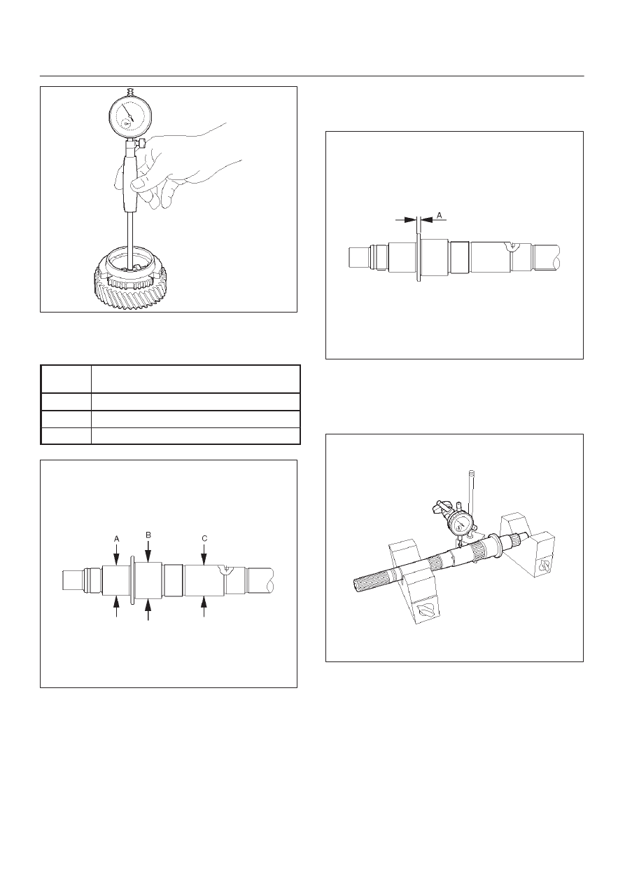
6. Inspect gear inside diameter.
1. Using a inside dial indicator, measure the gear
inside diameter.
Gear
Standard Diameter
1st
46.015 – 46.040 mm (1.8116 – 1.8126 in)
2nd
53.015 – 53.040 mm (2.0872 – 2.0882 in)
3rd
44.015 – 44.040 mm (1.7329 – 1.7339 in)
7B–44 MANUAL TRANSMISSION
226RW096
7. Inspect mainshaft.
1. Using a micrometer, measure the outer diameter
of the mainshaft journal.
Measure
Position
Standard
A
37.984 – 38.000 mm (1.4954 – 1.4961 in)
B
46.984 – 47.000 mm (1.8498 – 1.8504 in)
C
38.979 – 38.995 mm (1.5346 – 1.5352 in)
226RW078
2. Using a micrometer, measure the mainshaft
flange thickness.
Standard: 5.0 mm (0.197 in)
226RW079
3. Install the mainshaft to V-blocks.
4. Use a dial indicator to measure the mainshaft
central portion run-out.
Standard: less than 0.015 mm (0.0006 in)
226RW097
MANUAL TRANSMISSION
7B–45
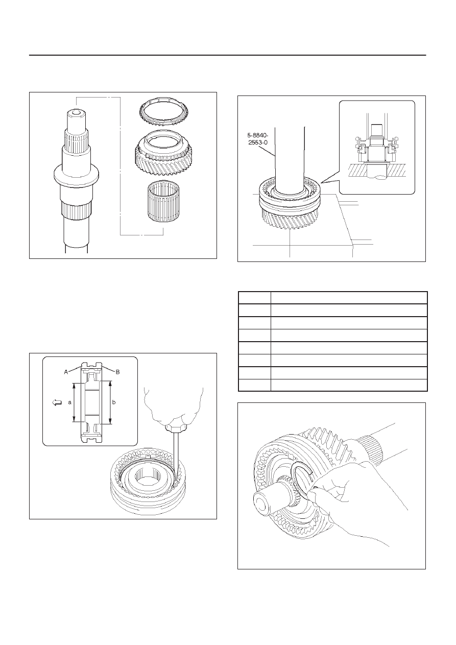
8. Install 3rd gear.
1. Install the 3rd gear needle bearing, 3rd gear and
3rd block ring to the mainshaft.
226RW098
9. Install the clutch hub No.2.
1. Install the clutch hub No.2 and hub sleeve No.2.
NOTE: Be careful the direction of the clutch hub No.2, as
shown.
2. Using a screwdriver, install 3 inserts and 2
springs.
NOTE: Position the insert springs so that their end gaps
are not in line.
226RW099
3. Using installer 5–8840–2553–0 (J–42797) and a
press, install the clutch nob No.2 and hub sleeve
No.2 to the mainshaft.
NOTE:
D
Align the brock ring slots with the inserts.
D
Check that the gear rotates smoothly.
226RW206
4. Select a snap ring that will allow minimum axial
play.
Mark
Thickness
A
1.80 – 1.85 mm (0.071 – 0.073 in)
B
1.85 – 1.90 mm (0.073 – 0.075 in)
C
1.90 – 1.95 mm (0.075 – 0.077 in)
D
1.95 – 2.00 mm (0.077 – 0.079 in)
E
2.00 – 2.05 mm (0.079 – 0.081 in)
F
2.05 – 2.10 mm (0.081 – 0.083 in)
G
2.10 – 2.15 mm (0.083 – 0.085 in)
226RW102
Нет комментариевНе стесняйтесь поделиться с нами вашим ценным мнением.
Текст