Opel Frontera UBS. Service manual — part 206
5A–37
BRAKE CONTROL SYSTEM
Step
No
Yes
Action
5
Is front 4WD controller normal?
Replace EHCU.
Go to Step 9
Replace 4WD
controller or
repair harness.
Go to Step 9
6
Is transmission input normal? (Chart C-2 or TC-2)
Go to Step 7
Replace SW or
repair harness
Go to Step 9
7
Is front 4WD controller normal?
Go to Step 8
Replace 4WD
controller or
repair harness.
Go to Step 9
8
Is hydraulic unit grounded properly?
Replace EHCU.
Go to Step 9
Correct.
Go to Step 9
9
Reconnect all components, ensure all components are properly
mounted.
Was this step finished?
Repeat the “Basic
diagnostic flow
chart.”
Go to Step 9
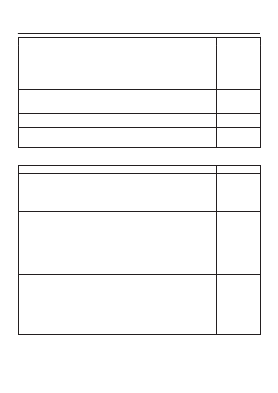
Chart A-4 Brake Pedal Feed Is Abnormal
Step
Action
Yes
No
1
Is the stop light actuated when the brake pedal is depressed?
Go to Step 2
Go to Step 3
2
1. Turn the ignition switch off.
2. Disconnected EHCU connector.
3. Measure voltage between the EHCU connector terminal 10
and 15 when brake pedal is depressed.
Is the voltage equal to the battery voltage?
Go to Step 4
Harness NG
between brake
SW and EHCU.
Go to Step 7
3
Is stop light fuse C-14 normal?
Go to Step 5
Replace fuse
C-14.
Go to Step 7
4
Is there continuity between EHCU connector terminals, 12 and 15
to body ground?
Go to Step 6
Repair body
grounded
harness.
Go to Step 7
5
Is the brake SW normal?
Repair stop light
harness.
Go to Step 7
Replace brake
SW.
Go to Step 7
6
Is the check harness/connector for suspended disconnection?
Hydraulic system
leakage or air
entry (Refer to
servicing
“Leakage or
brake fluid” )
Go to Step 7
Repair harness.
Go to Step 7
7
Reconnect all components and ensure all components are
properly mounted.
Was this step finished?
Repeat the “Basic
diagnostic flow
chart.”
Go to Step 7

5A–38
BRAKE CONTROL SYSTEM
Chart A-5, TA-5 Braking Sound (From EHCU) Is Heard While Not Braking
Step
Action
Yes
No
1
Is this the first time the vehicle is being driven after starting the
engine?
It is self checking
sound.
Normal.
Go to Step 2
2
Is vehicle speed under 10 km/h (6 mph)?
It is self checking
sound.
Normal.
Go to Step 3
3
Check for the following condition:
D
At the time of shift down or clutch operation.
D
At the time of low
m
drive (ice or snow road) or rough road drive.
D
At the time of high-speed turn.
D
At the time of passing curb.
D
At the time of operating electrical equipment switches.
D
At the time of racing the engine (over 5000 rpm).
Did it occur under any one condition above?
ABS may
sometime be
actuated even
when brake pedal
is not applied.
Go to Step 4
4
Is there play in each sensor/wheel speed sensor rings?
Go to Step 5
Repair.
Go to Step 7
5
Damage or powdered iron sticking to each sensor/wheel speed
sensor ring?
Go to Step 6
Repair.
Go to Step 7
6
Is each sensor output normal?(Refer to chart C-1 or TC-1).
Check harness/
connector for
suspected
disconnection.
If no
disconnection is
found, replace
EHCU.
Go to Step 7
Repair.
Go to Step 7
7
Reconnect all components, ensure all components are properly
mounted.
Was this step finished?
Repeat the “Basic
diagnostic flow
chart.”
Go to Step 7

5A–39
BRAKE CONTROL SYSTEM
Diagnostic Trouble Codes
Choose and trace an appropriate flowchart by the
numbers listed below to find fault and repair.
Code
Item
Diagnosis
Chart No.
12
Start Code
Normal
—
14
EHCU Function
Abnormality in input/output, operational and
control circuits
B-2
15
Power Voltage Drop
B-3
16
CLASS–2 Communication Line Ab-
normality
B-4
21
G-sensor
Wiring disconnection
B-5
23
Transmission Input
Input abnormality
B-6
24
Transfer Monitor
B-7
32
Motor & Motor Relay
Shorted or disconnected coil
B-8
35
Valve Relay
Shorted or disconnected coil/wiring
B-9
41
FL Holding Solenoid Valve
Shorted or disconnected coil/wiring
B-10
42
FL Decompression Solenoid Valve
Shorted or disconnected coil/wiring
B-11
43
FR Holding Solenoid Valve
Shorted or disconnected coil/wiring
B-12
44
FR Decompression Solenoid Valve
Shorted or disconnected coil/wiring
B-13
45
Rear Holding Solenoid Valve
Shorted or disconnected coil/wiring
B-14
46
Rear Decompression Solenoid Valve
Shorted or disconnected coil/wiring
B-15
51
FL Wheel Speed Sensor
Disconnected coil/wiring
B-16
52
FR Wheel Speed Sensor
Disconnected coil/wiring
B-17
53
RL Wheel Speed Sensor
Disconnected coil/wiring
B-18
54
RR Wheel Speed Sensor
Disconnected coil/wiring
B-19
61
FL Wheel Speed Sensor
Shorted coil/wiring
B-20
62
FR Wheel Speed Sensor
Shorted coil/wiring
B-21
63
RL Wheel Speed Sensor
Shorted coil/wiring
B-22
64
RR Wheel Speed Sensor
Shorted coil/wiring
B-23
65
Sensor Signal Input
Wrong number of teeth
B-24
5A–40
BRAKE CONTROL SYSTEM
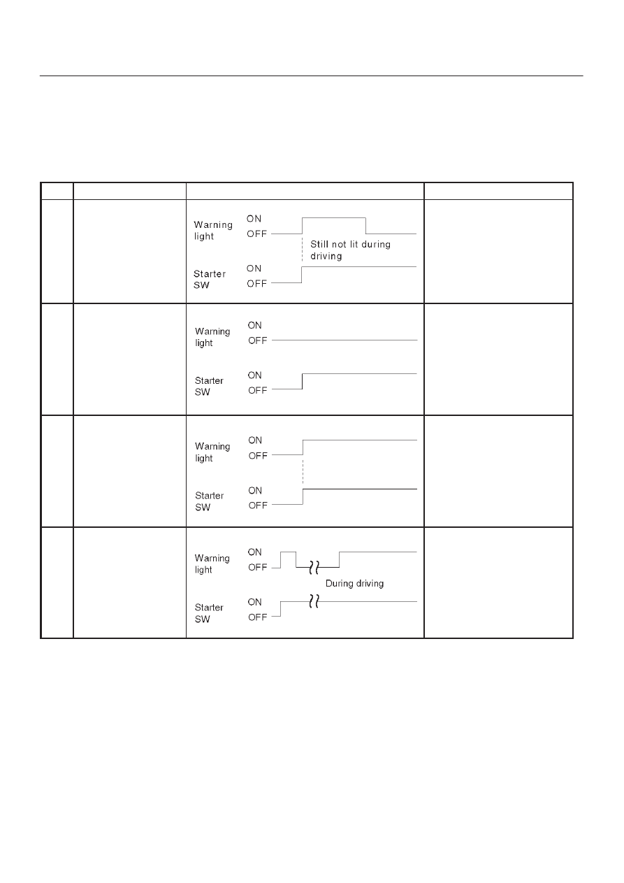
Diagnosis By “ABS” Warning Light
Illumination Pattern
In the event that there is abnormality in the “ABS” warning
light illumination pattern while the key is in the ON position
or if the warning light is actuated during driving, trouble
should be diagnosed on a illumination pattern basis as
follows:
No.
Condition
“ABS” Warning Light Illumination Pattern
Diagnostic
1
Warning light is actu-
ated normally
Normal
2
Warning light is not lit
Warning light lighting circuit
trouble
→
Go to Chart B-1
3
Warning light remains
ON
Diagnostic trouble codes are
stored.
Display diagnostic trouble
codes and diagnose on a
code basis according to the
flow charts.
4
Warning light is actu-
ated while driving
Diagnostic trouble codes are
stored.
Display diagnostic trouble
codes and diagnose on a
code basis according to the
flow charts.
Diagnostic Trouble Codes (DTCs)
When the warning light in the meter remains ON, the
EHCU stores the fault identification and disables the
ABS.
1. How to display and erase DTCs:
NOTE:
D
If DTCs are not displayed, harness C-4 connector
terminal 30 and I-10 connector terminal 2 may be
disconnected. Repair the harness and try DTC
display again.
D
DTCs can be displayed also by TECH 2. Select mode
“F0: Diagnostic Trouble Codes” from Application
Menu.
1. How to start DTC display:
D
Confirm that the vehicle has come to a complete
stop (with the wheels standing still) and that the
brake pedal is not depressed. (Unless these two
conditions are satisfied, DTC display cannot be
started.)
D
With IGN OFF, connect #12 terminal with #4
terminal or # 5 terminal (GND) . Then turn IGN ON.
Нет комментариевНе стесняйтесь поделиться с нами вашим ценным мнением.
Текст