Opel Frontera UBS. Service manual — part 2396
6A – 58 ENGINE MECHANICAL
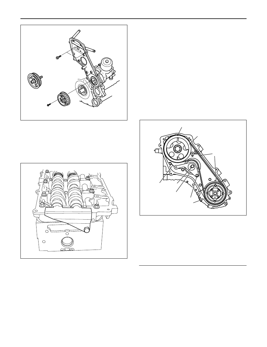
14. Camshaft pulley
1) Align TDC mark with crankshaft pulley and gear
case cover.
2) Set camshaft stopper on the end of intake and
exhaust camshaft.
Camshaft Stopper: 5-8840-2592-0
3) Install key to camshaft and install camshaft
pulley.
4) Apply engine oil to camshaft pulley fixing bolt
and tighten bolt with angular tightening method.
First step: 40 N·m (4.1 kg·m / 30 lb ft)
Second step: 60° to 90°
15. Timing belt
1) Install tensioner and tighten the bolt temporarily.
2) Align timing mark with camshaft pulley timing
mark and timing gear case timing mark.
3) Set No.1 cylinder TDC position.
4) Install the timing belt in the following order
camshaft pulley, oil pump pulley, tensioner.
NOTE:
1) It is recommended for easy installation that the belt
be secured with a double clip after it is installed to
each pulley.
2) The “ISUZU” mark should be read from the front of
the engine when installing the timing belt.
5) Install the belt tensioner.
6) Conform not phase difference each pulley.
7) Tension the timing belt with two turns of the
crankshaft.
8) Tighten the tensioner bolt in order A to B to the
specified torque.
Torque: Bolt A 50 N·m (5.1 kg·m/37 lb ft)
Bolt B 20 N·m (2.0 kg·m/14 lb ft)
Legend
(1) Align Mark
(2) Camshaft Pulley
(3) Timing Belt
(4) Oil Pump Pulley
(5) Tension Bolt B
(6) Tensioner Assy
(7) Tensioner Bolt A
(8) Tensioner Spring
16. CMP sensor bracket
1) Install CMP sensor bracket and tighten bolt to
the specified torque.
Torque: 20 N·m (2.0 kg·m / 14 lb ft)
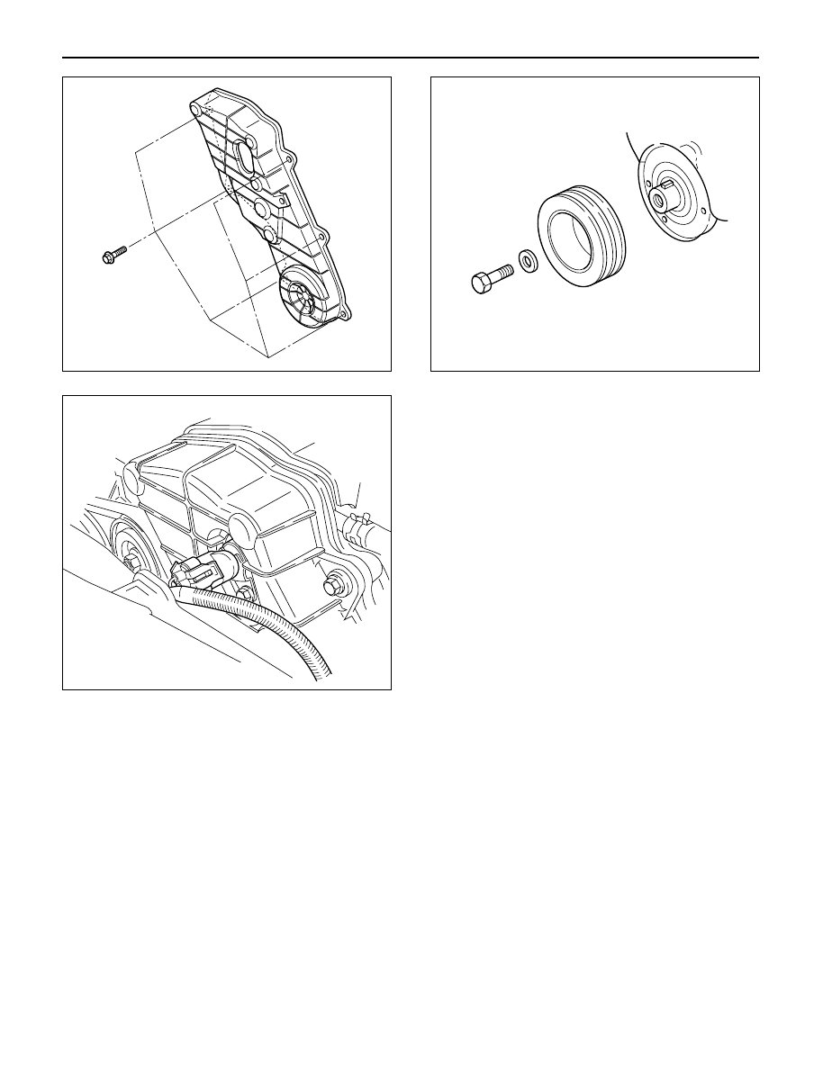
17. Timing belt cover
1) Install timing belt cover and tighten bolt to the
specified torque.
Torque: 9 N·m (0.9 kg·m / 78 lb in)
2) Tighten CMP sensor to the specified torque.
Torque: 9 N·m (0.9 kg·m / 78 lb in)
012RW036
012RW099
1
2
3
8
6
7
4
5
F06R200006
ENGINE MECHANICAL 6A – 59
18. Crankshaft damper pulley
1) Insert damper pulley with the crankshaft key
groove set on the key.
2) Tighten damper pulley bolt to the specified
torque.
Torque: 216 N·m (22 kg·m / 159 lb ft)
19. Cooling fan Assembly
1) Install the cooling fan assembly to the fan pulley,
tighten the nuts to the specified torque.
Torque: 8 N·m (0.8 kg·m / 69 lb in)
20. AC generator drive belt.
1) Temporarily tighten generator fixing bolts and
belt tensioner adjustment plate.
2) Tension the generator drive belt then tighten the
generator fixing bolt.
Torque: 40 N·m (4.1 kg·m / 30 lb ft)
3) Tighten the belt tensioner adjustment plate bolt.
Torque: 20 N·m (2.0 kg·m / 14 lb ft)
012RW039
014RW163
012RW032
6A – 60 ENGINE MECHANICAL
VALVE STEM SEAL, VALVE SPRING AND ADJUSTER
REMOVAL
1. Disconnect battery ground cable.
2. Drain engine coolant.
3. Remove the air duct from between air cleaner and
turbocharger.
4. Remove intercooler assembly.
Refer to “Intercooler” in this manual.
5. Remove oil level gauge guide assembly.
6. Disconnect PCV hose.
7. Disconnect EGR vacuum hose.
8. Disconnect harness connectors around the cylinder
head such as the injector, CMP sensor, MAP
sensor, EGR sensor, EVRV, IAT sensor, A/C
compressor, TP stepping motor, TP sensor and fuel
temperature sensor etc.
9. Remove A/C compressor assembly.
10. Remove A/C compressor bracket.
11. Remove generator assembly and take out drive
belt.
12. Remove heat protector, remove exhaust valve
assembly.
13. Remove water cooling hose and lubrication pipe for
turbocharger.
14. Remove turbocharger assembly.
15. Remove hose between thermostat and radiator.
16. Remove noise insulator cover of cylinder head.
NOTE: Do not damage injector harness.
17. Remove high pressure oil pipe.
18. Remove timing belt cover.
19. Remove CMP sensor bracket.
20. Remove timing belt tensioner then remove timing
belt.
21. Remove camshaft pulley.
22. Remove front plate.
23. Remove engine coolant pipe between cylinder
head and water pump.
1
2
3
4
5
6
9
10
7
8
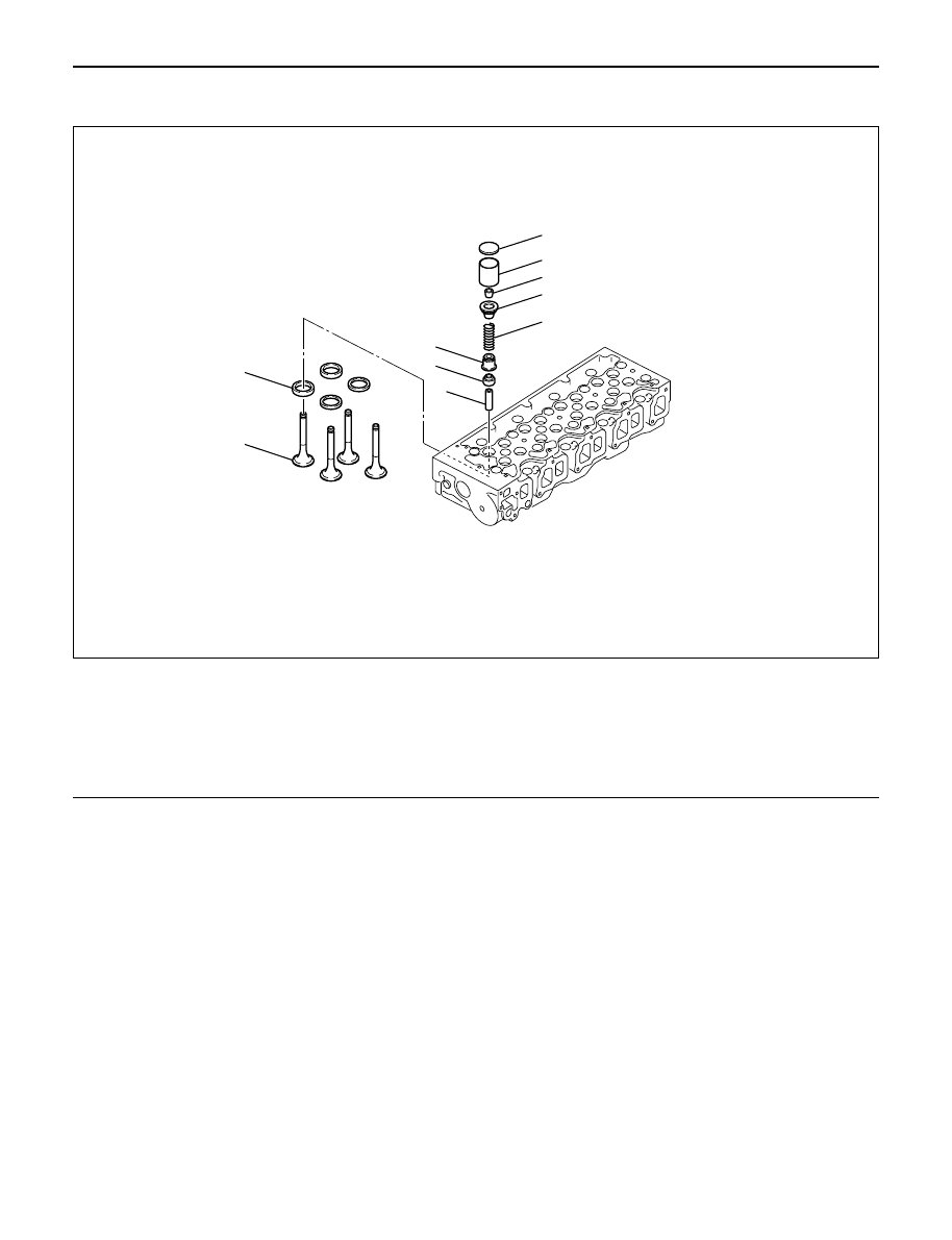
011RW031
Legend
(1)
Adjuster
(2)
Tappet
(3)
Split Collar
(4)
Spring Seat Upper
(5)
Valve Spring
(6)
Spring Seat Lower
(7)
Valve Stem Seal
(8)
Valve Guide
(9)
Valve Seat
(10)
Valve
ENGINE MECHANICAL 6A – 61
24. Remove fuel pipe between fuel pump and intake
manifold.
25. Remove fuel return pipe from rear of cylinder head.
26. Remove intake manifold assembly.
27. Disconnect glow plug harness and remove glow
plug.
28. Remove cylinder head cover.
29. Remove injector harness connector.
30. Disconnect harness connector from oil pressure
sensor and oil temperature sensor on the oil rail.
31. Remove injector harness assembly.
32. Remove injector clamp.
33. Remove injector is fixed bolts.
34. Remove injector assembly.
35. Remove oil rail.
36. Remove camshaft carrier assembly with camshaft.
37. Remove cylinder head assembly.
38. Disassemble valve spring according to the following
method.
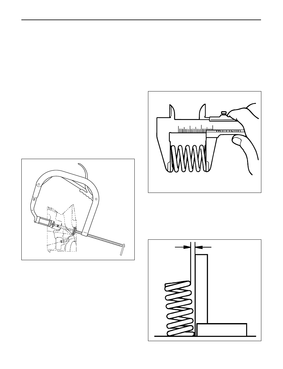
1) Use valve spring compressor then remove split
collars.
2) Valve spring compressor: 5-8840-2441-0
NOTE: Put removed valve spring in order of cylinder
number.
39. Valve stem seal.
1) Use a screwdriver or pliers to remove valve
stem seal.
NOTE: Do not reuse removed valve stem seal.
INSPECTION AND REPAIR
Make the necessary adjustments, repairs and part
replacements if excessive wear or damage is
discovered during inspection.
Valve spring
CAUTION: Visually inspect the valve springs and
replace them if damage or abnormal wear is
evident.
1. Free height
1) Measure the free height of the springs. The
springs must be replaced if the height is below
the specified limit.
Standard: 45.85 mm (1.8051in)
Limit: 43.9 mm (1.7283 in)
2. Squareness
1) Measure the valve spring squareness with a
steel square.
2) Replace the valve springs if the measured value
exceeds the specified limit.
Limit: 1.6 mm (0.063 in)
014rw042
014rs004
014rs005
Нет комментариевНе стесняйтесь поделиться с нами вашим ценным мнением.
Текст