Opel Frontera UBS. Service manual — part 158
DRIVE LINE CONTROL SYSTEM (TOD)
4B2–84
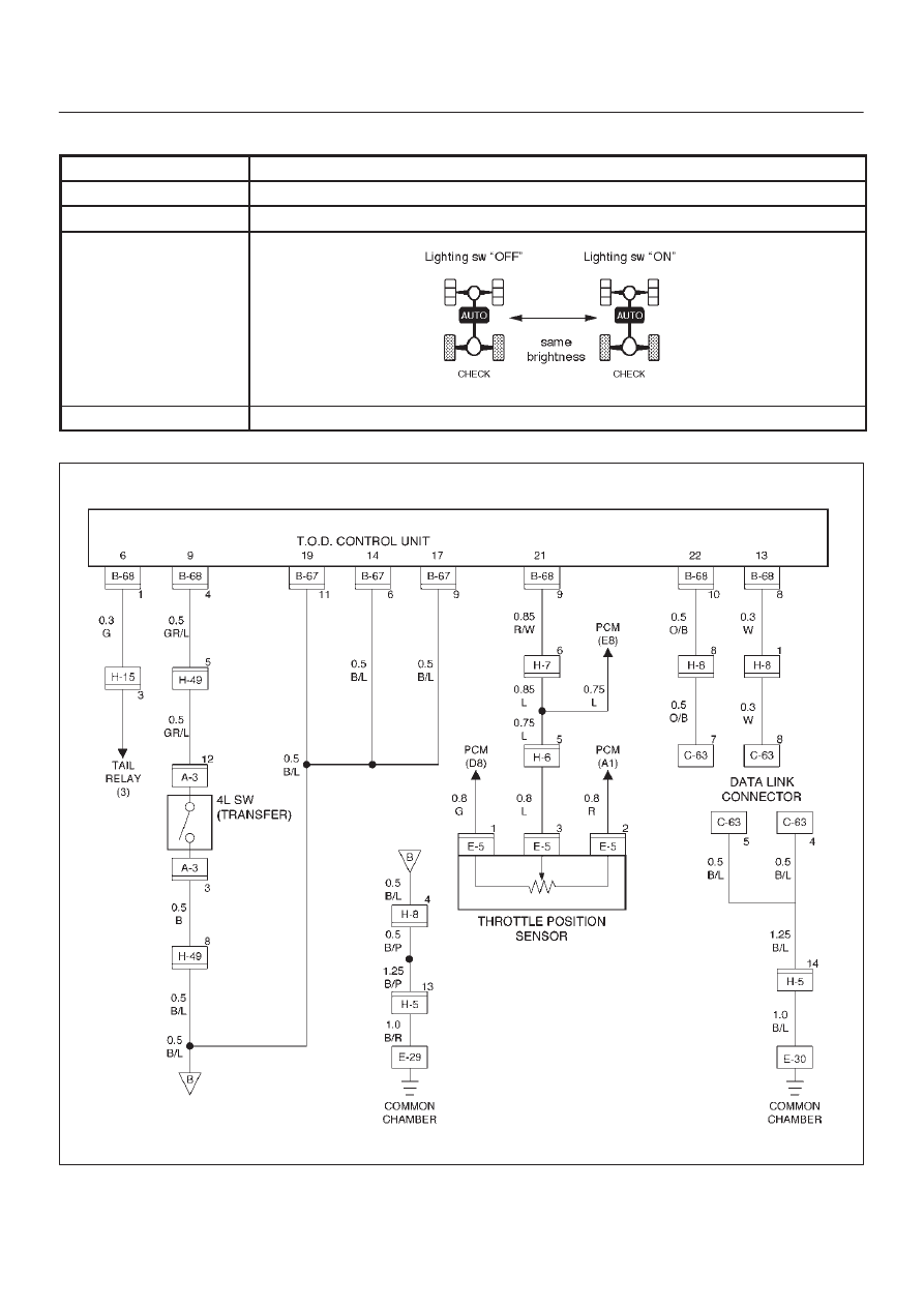
Chart H
lighting switch circuit
Function of circuit
Reads in the status of lighting switch and reduces the indicator brightness at night.
Fail condition
Even if the lighting switch is pressed on and off, brightness does not change.
Indicator lamp status
Transfer position
All position (example TOD mode)
D04RW056

4B2–85
DRIVE LINE CONTROL SYSTEM (TOD)
Step
Action
Yes
No
1
1. Disconnect ECU terminal.
2. Turn on the starter switch.
Is battery voltage observed between ECU terminals (B–68)1 and
(B–67)11?
Go to Step 2
Wirers are broken
lighting SW
circuit. Repair
the circuit.
Go to Step 4
2
Turn lighting SW “ON”.
Is 0 V observed between ECU terminal (B–68)1 and (B–67)11?
Go to Step 3
Lighting SW
circuit battery
short. Repair the
circuit.
Go to Step 4
3
Connect ECU terminal.
While the lighting switch is pressed on and off, does the
brightness of the indicator change?
The phenomenon
is not
reproduced.
Refer to
“Troubles
intermittently
observed”
Go to Step 4
The ECU has
failed. Replace
the ECU.
Go to Step 4
4
Check that all the parts are mounted.
Is this step complete?
Repeat the
“Diagnosis Flow”.
Return to Step 4

DRIVE LINE CONTROL SYSTEM (TOD)
4B2–86
Diagnosis from Symptom
Troubles that are not indicated by the warning lamp are
listed in the table below. These troubles are caused by
the faults that cannot be detected by the self-diagnostic
function of the control unit.
If this type of trouble is observed, interview the customer
and conduct test runs to reproduce the trouble,
cross-check the reported trouble with the listed
phenomena, and diagnose and analyze the trouble on the
item by item basis.
Phenomena
Major cause
Corrective action
1
The tight corner braking is ob-
served when the vehicle is subject
to full steering.
D
The standard tires are not used.
D
The tire pressure is incorrect.
D
The tires are worn inuniformity.
D
The transfer or wiring is
imperfect.
D
The limited slip differential is
failed.
Check and recondition the ve-
hicle according to Chart 1.
2
Even if the 4WD SW is select to the
4WD position, the 4WD mode is not
active, resulting in remarkable rear
wheel spin.
D
The transfer or wiring is
imperfect.
D
The shift on the fly system is
failed.
Check and recondition the ve-
hicle according to Chart 2.
3
D
When the 4WD SW is select to
the 4WD position, the drive
resistance of the 4WD system is
too large to get sufficient running
speed.
D
Noised drive line.
D
The standard tires are not used.
D
The tire pressure is incorrect.
D
The tires are worn inuniformity.
D
The transfer or wiring is
imperfect.
D
The limited slip differential is
Check and recondition the ve-
hicle according to Chart 1.
4
The shift on the fly system (front
axle) generates gear noises.
D
The wiring is imperfect.
D
The full automatic free wheel
hub is failed.
Check and recondition the ve-
hicle according to Chart 3.
5
The braking distance gets long
even when the ABS is active.
D
The wiring is imperfect.
D
The ABS is failed.
Check and recondition the ve-
hicle according to Chart 4.
4B2–87
DRIVE LINE CONTROL SYSTEM (TOD)
Chart 1
The tight corner braking is observed.
Function of circuit
—
Fail condition
When the vehicle is subject to full steering in the TOD mode, the drive resistance gets
large or the judder occurs. Otherwise, the above phenomenon is observed only when the
brake is applied.
D04RW057
Нет комментариевНе стесняйтесь поделиться с нами вашим ценным мнением.
Текст