Opel Frontera UBS. Service manual — part 923
1B–86 AIR CONDITIONING
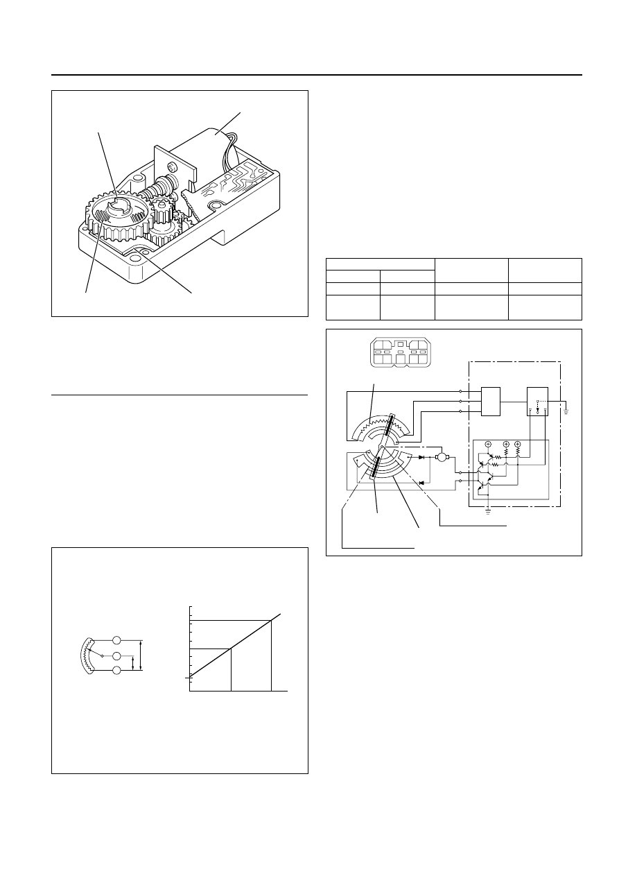
Legend
(1)
Out put Axis
(2)
Motor
(3)
Printed Circuit Board
(4)
Sliding Contact
The mode and mix actuators are common actuators
with the built-in potentiometer. For the intake
actuator, the contact switch type is selected.
The potentiometer is a register assembled to the
printed circuit board of the mix and mode
actuators. It detects the air mix door position
specified by rotation of the output axis as a ratio of
the variable terminal (VM) voltage against the
reference voltage (VDD: 5V), then signals the value
to the automatic heater/air conditioner control unit.
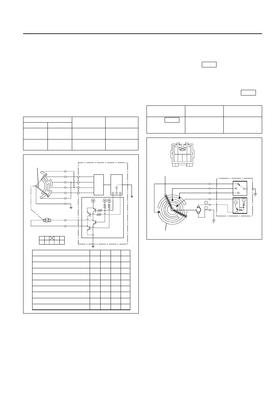
• Movement of Mix Actuator
Position of the air mix door is determined by the
controller on the automatic heater/air conditioner
control unit.
As the heat or cool side of the controller is
grounded, the transistor on the driver is activated
and, thus, the motor rotation is turned on. The
sliding contact connected to the motor sends the
position detection signal from the potentiometer
to the automatic heater/air conditioner control
unit. As the set temperature and interior
temperature are balanced, the controller returns
to the neutral and the motor rotation is stopped.
1
2
4
3
860RW026
C01RX016
M
N
3
2
7
6
8
9 8
4 3
6 5
2 1
7
Potentiometer
Connection
Position
Detection
Block
Automatic Heater / Air
Conditioner Control Unit
Controller
Sliding Contact
Full Heat Position
Terminal Plate
Full Cool Position
Driver
Cool Side
Heat Side
C01RY00016
Full cool
Full cool
0
0
0.5
1.0
50
100%
Aperture of air mix door
V
oltage r
atio
VM/VDD
Full heat
Full heat
VDD
VM
+
–
I-45
Rotation
(+) side
(–) side
direction
Remarks
8
6
Clockwise
Full heat side
6
8
Counter
Full cool side
clockwise
AIR CONDITIONING 1B–87
• Movement of Mode Actuator
As target position of the mode door is decided on
the controller of the control unit, the control unit
reads the position detection signal from the
actuator to select the clockwise or counter
clockwise motor rotation direction.
Grounding the controller VENT or DEF side after
the direction selection activates the transistor on
the driver, thus turning on the motor rotation.
Accompanying the motor rotation, the sliding
contact rotates, too. When the target position is
reached, the controller on the control unit returns
to the neutral and the motor stops.
• Movement of Intake Actuator
The controller on the automatic heater/air
conditioner control unit selects an intake mode to
be used.
As the Terminal No.5
is grounded via the
sliding contact on the terminal plate, the
transistor on the driver is activated, thus turning
on the motor rotation. Then, accompanying
move of the motor, the sliding contact rotates
until grounding of the Terminal No.5
is
removed, thus stopping the motor.
I-49
I-49
Driver
Controller
DEF side
VENT side
Position
detection
block
Control unit
Sliding
contact
Actuator side
4
2
9 8
3
7
7
8
9
10
H
L
H
L
H
H
H
L
H
H
L
L
H
H
L
H
H
L
L
H
H
L
H
H
L
L
H
H
L
H
H
H
L
H
L
H
6
1
5
Interconnected
motor
VENT
VENT
Mid point between VENT - B/L
B/L
Mid point between B/L - FOOT
FOOT
Mid point between FOOT - D/F
D/F
Mid point between D/F - DEF
DEF
DEF
7
8
9
10
2
6
7
8
3
4
9
5
1
C01RX017
M
+
6
1
2
6 5 4 3
REC
MIX
FRESH
Com
1
2
5
3
4
+
+
—
Terminal Plate
Auto A/C
Control Unit
(Actuator Side)
Driver
Controller
Sliding Contact
Connected
C01RX006
Conducting pin
Rotation
(+) side
(–) side
direction
Remarks
5
1
Clockwise
VENT to
DEF direction
1
5
Counter
DEF to
clockwise
VENT diction
Grounding
Rotation
terminal
direction
Remarks
No.5
Clockwise
RE-CIRCULA
TION
→
MIX
→
FRESH
I-49
1B–88 AIR CONDITIONING
OVERVIEW OF AUTOMATIC CONTROL OF
FULL AUTOMATIC AIR CONDITIONER
The full automatic heater and air conditioner on this
vehicle has the following features:
• Interior temperature control.
• Air flow control.
• Mode (blow port) control.
• Intake (switching between fresh air and interior
air) control.
• Heater start timing control.
• Cooler start timing control.
• Evaporator anti-freeze control.
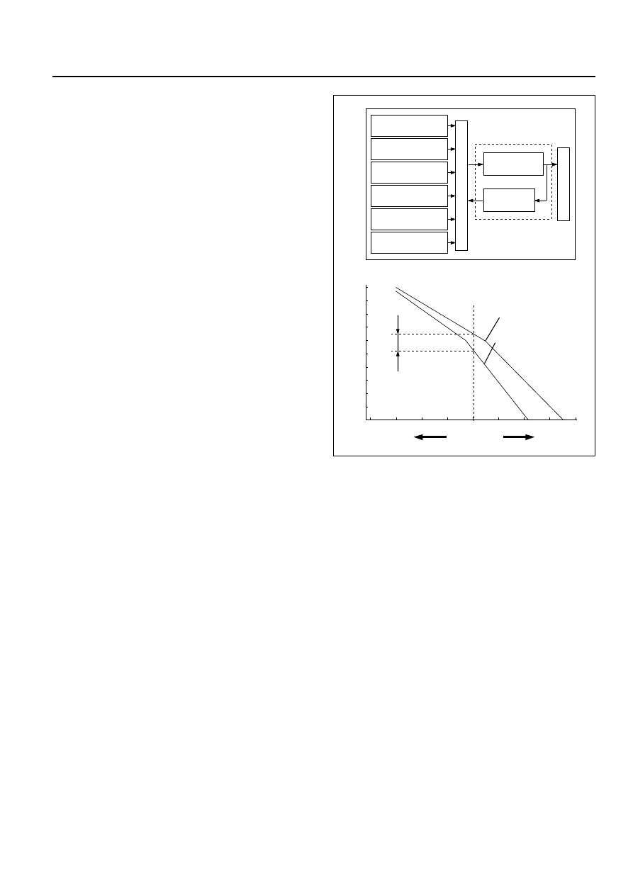
1. Interior Temperature Control
The automatic heater/air conditioner control unit
operates on the setup temperature signal from
the temperature control switch and other sensor
signals to derive the total signal. Then, the
control unit compares this signal against the
signal from the potentiometer to determine
rotation direction of the mix actuator. The mix
actuator moves the air mix door to the aperture
specified by the total signal so that the specified
interior temperature is achieved.
If the compressor is turned off in the A/C (air
conditioning) mode, aperture of the air mix door
is offset according to the outside air temperature
or the specified interior temperature. This
function removes the difference in the blowing
temperature in this state and that of when the
compressor is turned on.
When FH or FC is selected for the setup
temperature, the air mix door is accordingly
fixed to the Full Heat or Full Cool mode.
When the VENT mode is selected, aperture of
the air mix door is controlled so that excessively
heated air may not be blown from the VENT
blow port.
0
50
140
104
68
32
Air mix door aperture
Full cool
Heater
side
Restriction on the
aperture enabied
in the VENT mode
Air conditioning
ON mode
Full heat
Set temperature
signal
Mix
actuator
Potentio
meter
Air mix door
In car sensor
Ambient sensor
Sun sensor
Control unit
Air conditioning
switch
Set up temperature
signal
Air conditioning
OFF mode
Total signal
Cooler
side
C01RY00011
AIR CONDITIONING 1B–89
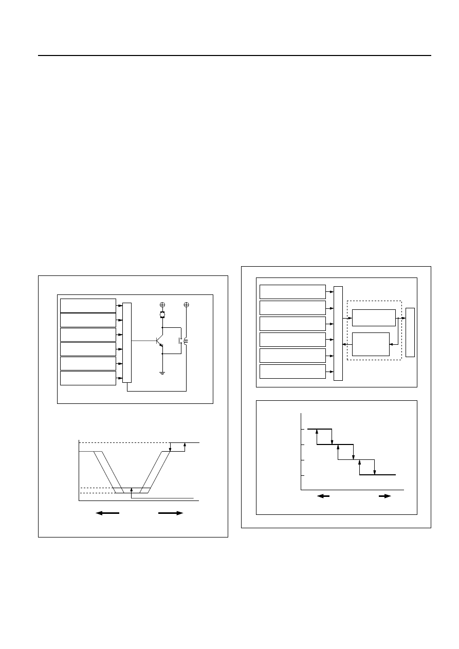
2. Air Flow Control
• In the Auto Mode
The automatic heater/air conditioner control unit
operates on the setup temperature signal and
other sensor signals to derive the total signal.
Then, the control unit adjusts base potential of
the power transistor to match it to the voltage
pattern of the target fan so that stage-less fan
speed control can be achieved.
When solar radiation quantity is detected in the
VENT or B/L mode, the control unit increases the
minimum fan voltage to offset.
When FH or FC is selected from the temperature
control switch, air flow is accordingly fixed to
MAX HI or AUTO HI.
• In the Manual Mode
Air flow specified from the fan switch is entered
to the automatic heater/air conditioner control
unit as the manual signal. The signal modifies
the air flow to the level specified from the fan
switch so that the required fan voltage is
attained.
3. Mode (Blow Port) Control
The automatic heater/air conditioner control unit
operates on the setup temperature from the
control switch, and temperature and solar
radiation quantify from the sensors to determine
the total mode control signal. According to the
pattern specified by this signal, the control unit
selects either one of the VENT, BI-LEVEL, FOOT
or DEF/FOOT mode.
The mode actuator determines the rotation
direction comparing the target position against
the current position being determined by the
position detection signal.
When FH or FC is selected for the temperature
from the temperature control switch, mode is
accordingly fixed to the VENT or FOOT.
• In the manual operation of the mode switch, you
can select a desired blow port mode pressing
the corresponding mode switch.
• Operating the DEF mode switch selects the DEF
for the blow port mode.
4.5
12
(V)
M
MAX
HI Relay
Power
transistor
4.8
10.5
MAX HI
Set up
temperature signal
Control unit
In car sensor
Ambient sensor
Sun sensor
Mode control
signal
Fan switch
AUTO HI
Heater
side
Cooler
side
Total signal
VENT mode
Blower fan motor terminal voltage
C01RY00008
Mode control
DEF / FOOT
Set up temperature
signal
Mode actuator
Mode door
Position
detection
switch
Control unit
In car sensor
Sun sensor
Air conditioning
switch
Mode control
signal
Ambient sensor
FOOT
BI-LEVEL
VENT
Heater
side
Cooler
side
Mode total signal
C01RY00009
Нет комментариевНе стесняйтесь поделиться с нами вашим ценным мнением.
Текст