Opel Frontera UBS. Service manual — part 2920
SUPPLEMENTAL RESTRAINT SYSTEM
9J–33
Sensing And Diagnostic Module (SDM)
Service Precautions
WARNING: DURING SERVICE PROCEDURES, BE
VERY CAREFUL WHEN HANDLING SDM. NEVER
STRIKE OR JAR SDM. UNDER SOME
CIRCUMSTANCES, IT COULD CAUSE
DEPLOYMENT AND RESULT IN PERSONAL INJURY
OR IMPROPER OPERATION OF THE
SUPPLEMENTAL RESTRAINT SYSTEM (SRS) . SDM
MOUNTING BRACKET BOLTS MUST BE
CAREFULLY TORQUED TO ASSURE PROPER
OPERATION. NEVER POWER UP THE SRS WHEN
SDM IS NOT RIGIDLY ATTACHED TO THE VEHICLE.
THE SDM COULD BE ACTIVATED WHEN POWERED
WHILE NOT RIGIDLY ATTACHED TO THE VEHICLE
WHICH COULD CAUSE DEPLOYMENT AND RESULT
IN PERSONAL INJURY.
WARNING: PROPER OPERATION OF THE SENSING
AND DIAGNOSTIC MODULE (SDM) REQUIRES THE
SDM TO BE RIGIDLY ATTACHED TO THE VEHICLE
STRUCTURE AND THAT THE ARROW ON THE
SENSOR BE POINTING TOWARD THE FRONT OF
THE VEHICLE.
SDM is specifically calibrated and is keyed to the SDM
location SRS wiring harness. Caution should be used to
ensure proper location of the SDM. The keying of the
SDM to its location and wiring harness connectors should
never be modified in the field.
Removal
1. Disable the SRS (Refer to “Disabling the SRS” in this
section).
2. Remove the transmission knob (for M/T) and transfer
lever knob.
3. Remove the front console assembly and disconnect
wiring harness connector.
4. Pull CPA (Connector Position Assurance) out and
push connector lock down to disconnect the SDM
harness connector.
5. Remove the three SDM fixing bolts and remove SDM.
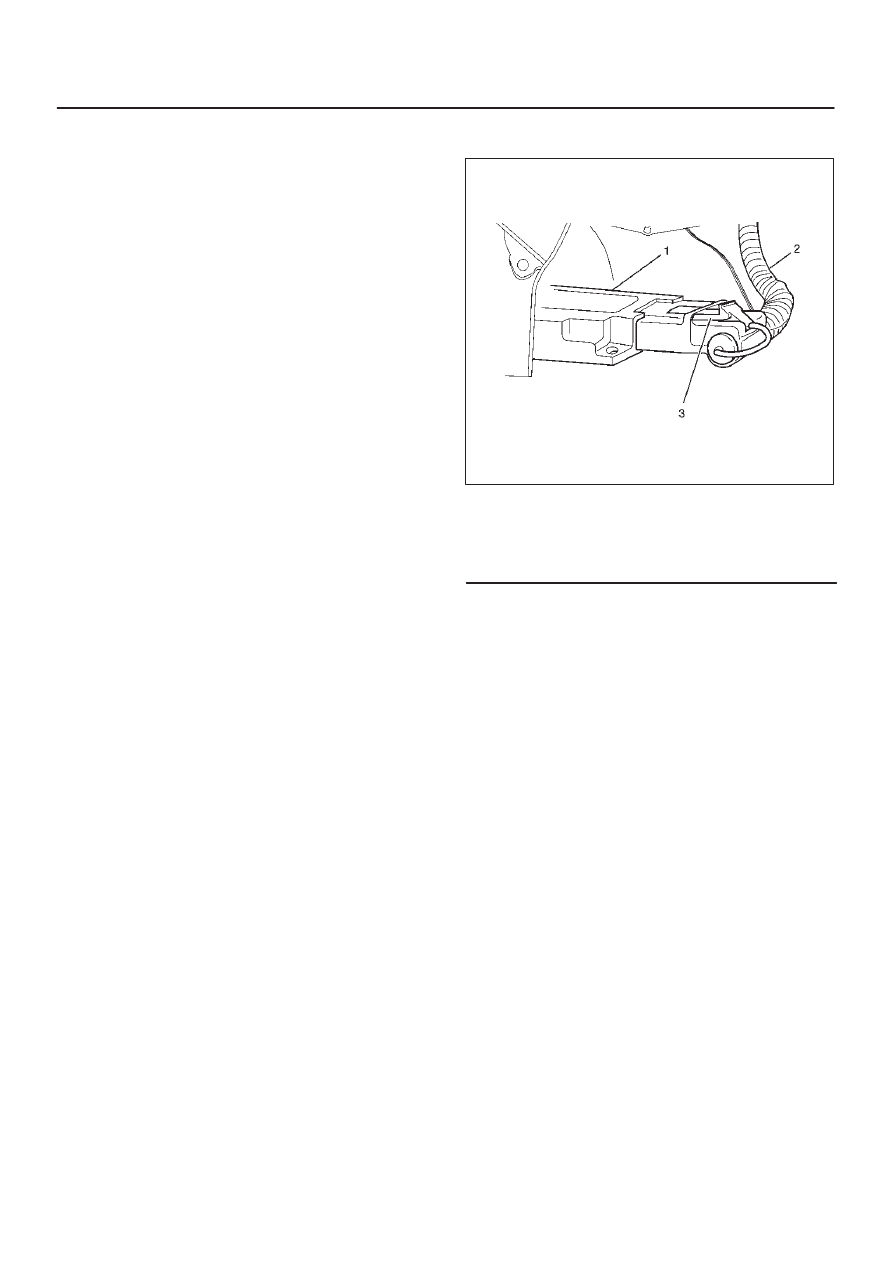
827RW044
Legend
(1) SDM
(2) SRS Harness
(3) Connector Position Assurance
Installation
1. Install the SDM on bracket and fixing bolts and tighten
the fixing bolts to the specified torque.
Torque: 10 N·m (1.0 Kg·m/87 Ib in)
2. Connect the SDM harness connector and after that,
put CPA into connector.
3. Install the front console.
4. Install the transmission knob (for M/T) and transfer
lever knob.
SUPPLEMENTAL RESTRAINT SYSTEM
9J–34
5. Enable the SRS (Refer to “Enabling the SRS” in this
section).
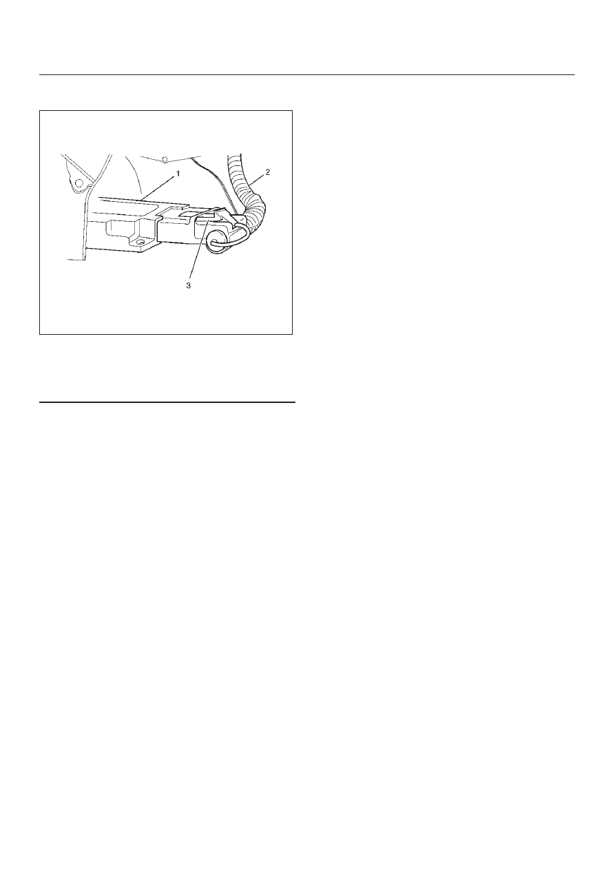
827RW044
Legend
(1) SDM
(2) SRS Harness
(3) Connector Position Assurance
SUPPLEMENTAL RESTRAINT SYSTEM
9J–35
Driver Air Bag Assembly
Service Precautions
WARNING: SAFETY PRECAUTIONS MUST BE
FOLLOWED WHEN HANDLING A DEPLOYED AIR
BAG ASSEMBLY. AFTER DEPLOYMENT, THE AIR
BAG ASSEMBLY SURFACE MAY CONTAIN A SMALL
AMOUNT OF SODIUM HYDROXIDE, A BY–PRODUCT
OF THE DEPLOYMENT REACTION, THAT IS
IRRITATING TO THE SKIN AND EYES. MOST OF THE
POWER ON THE AIR BAG ASSEMBLY IS
HARMLESS. AS A PRECAUTION, WEAR GLOVES
AND SAFETY GLASSES WHEN HANDLING A
DEPLOYED AIR BAG ASSEMBLY, AND WASH YOUR
HANDS WITH MILD SOAP AND WATER
AFTERWARDS.
WARNING: WHEN CARRYING A LIVE AIR BAG
ASSEMBLY, MAKE SURE THE BAG AND TRIM
COVER ARE POINTED AWAY FROM YOU. NEVER
CARRY AIR BAG ASSEMBLY BY THE WIRES OR
CONNECTOR ON THE UNDERSIDE OF MODULE. IN
THE CASE OF AN ACCIDENTAL DEPLOYMENT, THE
BAG WILL THEN DEPLOY WITH MINIMAL CHANCE
OF INJURY. WHEN PLACING ALIVE AIR BAG
ASSEMBLY ON A BENCH OR OTHER SURFACE,
ALWAYS FACE BAG AND TRIM COVER UP, AWAY
FROM THE SURFACE. NEVER REST A STEERING
COLUMN ASSEMBLY ON THE STEERING WHEEL
WITH THE AIR BAG ASSEMBLY FACE DOWN AND
COLUMN VERTICAL. THIS IS NECESSARY SO THAT
A FREE SPACE IS PROVIDED TO ALLOW THE AIR
BAG ASSEMBLY TO EXPAND IN THE UNLIKELY
EVENT OF ACCIDENTAL DEPLOYMENT.
OTHERWISE, PERSONAL INJURY COULD RESULT.
NOTE: In the event deployment has occurred, inspect
coil assembly wire for any signs of scorching, melting or
any other damage due to excessive heat. If the coil has
been damaged, replace it.
Removal
1. Disable the SRS (Refer to “Disabling the SRS” in this
section).
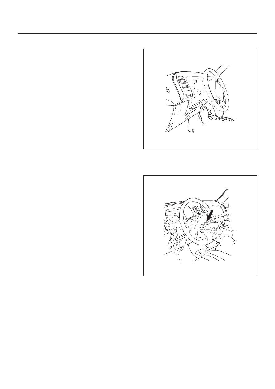
2. Loosen the air bag assembly fixing bolts from behind
the steering wheel assembly using a TORX
driver or
equivalent until the air bag assembly can be released
from steering wheel.
827RT008
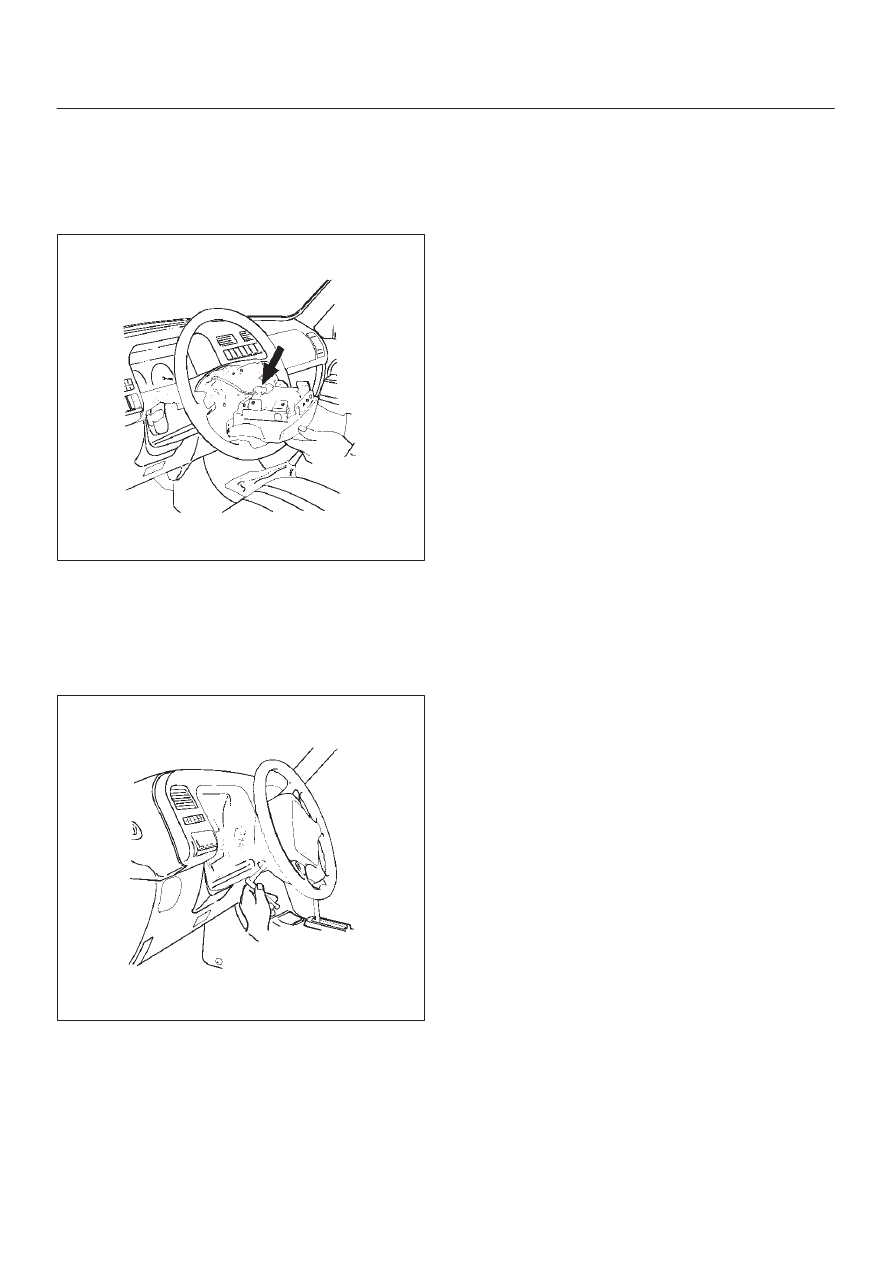
3. Disconnect the yellow 2–pin connector located
behind the air bag assembly and remove air bag
assembly. Refer to “SRS Connectors” in this section
for removal and installation.
827RT009
SUPPLEMENTAL RESTRAINT SYSTEM
9J–36
Installation
1. Connect air bag to wiring harness connector.
NOTE: Pass the lead wire through the tabs on the plastic
cover (wire protector) of air bag to prevent lead wire from
being pinched.
827RT009
2. Install air bag into steering wheel and tighten bolts to
specified sequence as shown in figure.
Torque: 8.8 N·m (0.9 Kg·m/78 Ib in)
CAUTION: Never use the air bag assembly from
another vehicle. Use only new air bag assembly
proper to the Trooper which is being repaired.
827RT008
3. Enable the SRS (Refer to “Enabling the SRS” in this
section).
Нет комментариевНе стесняйтесь поделиться с нами вашим ценным мнением.
Текст