Opel Frontera UBS. Service manual — part 300

6E–106
ENGINE DRIVEABILITY AND EMISSIONS
DTC P0101 – MAF System Performance
(Cont'd)
Step
No
Yes
Value(s)
Action
6
1. Ignition “ON,” engine “OFF.”
2. Review the Freeze Frame and/or Failure Records
data for this DTC and note parameters.
3. Ignition “OFF” for 15 seconds.
4. Start the engine and operate the vehicle within the
conditions required for this diagnostic to run, and as
close to the conditions recorded in Freeze Frame
/Failure Records possible. (Special operating
conditions that need to be met before the PCM will
run this diagnostic (where applicable) are listed in
“Conditions for Setting the DTC”).
5. Using the Tech 2, select “DTC,” then enter the DTC
number which was set.
Does the Tech 2 indicate that this diagnostic failed this
ignition?
—
Go to
Step 7
Refer to
Diagnostic
Aids
7
1. Check for the following conditions:
D
Objects blocking the MAF sensor inlet screen;
D
Intake manifold vacuum leaks;
D
Vacuum leaks at throttle body;
D
Vacuum leaks EGR value flange and pipes.
D
Crankcase ventilation valve faulty, missing, or
incorrectly installed.
2. If a problem is found, repair as necessary.
Was a problem found?
—
Verify repair
Go to
Step 8
8
1. Ignition “OFF.”
2. Disconnect the MAF sensor connector.
3. Ignition “ON,” engine “OFF.”
4. Using DVM 5-8840-0285-0, measure voltage
between the MAF sensor signal circuit and chassis
ground.
Is the voltage near the specified value?
5 V
Go to
Step 9
Go to
Step 10
9
Connect a test light (5-8840-0607-0) between the MAF
sensor ignition feed and ground circuits at the MAF
sensor harness connector.
Is the test light “ON?”
—
Go to
Step 13
Go to
Step 12
10
Is the voltage less than the specified value?
4.5 V
Go to
Step 13
Go to
Step 11
11
1. Ignition “OFF,” disconnect the PCM.
2. Ignition “ON,” engine “OFF.”
3. Measure voltage between the MAF signal circuit
and ground.
Does the voltage measure near the specified value?
0 V
Go to
Step 13
Go to
Step 12
12
Connect a test light (5-8840-0607-0) between the MAF
sensor ignition feed circuit and chassis ground.
Is the test light “ON?”
—
Go to
Step 13
Go to
Step 7
13
1. Check for a poor connection at the MAF sensor.
2. If a poor connection is found, replace faulty
terminal(s). Refer to
Repair Procedures in
Electrical Diagnosis (8A Cell 5).
Was a poor connection found?
—
Verify repair
Solved
6E–107
ENGINE DRIVEABILITY AND EMISSIONS
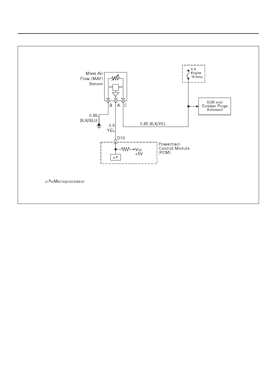
Diagnostic Trouble Code (DTC) P0102 MAF Sensor Circuit Low Frequency
T321122
Circuit Description
The mass air flow (MAF) sensor measures the amount of
air which passes through it into the engine during a given
time. The powertrain control module (PCM) uses the
mass air flow information to monitor engine operating
conditions for fuel delivery calculations. A large quantity
of air entering the engine indicates an acceleration or high
load situation, while a small quantity of air indicates
deceleration or idle.
The MAF sensor produces a frequency signal which can
be monitored using a Tech 2. The frequency will vary
within a range of around 2500 Hz at idle to around
1900 Hz at maximum engine load. DTC P0102 will be set
if the signal from the MAF sensor is below the possible
range of a normally operating MAF sensor.
Conditions for Setting the DTC
D
The engine is running above 500 RPM for greater than
10 seconds.
D
System voltage is above 11.5 volts.
D
MAF signal frequency is below 1000 Hz for a total of
50-percent of the last 1000 samples monitored. A
sample is taken every cylinder event.
Action Taken When the DTC Sets
D
The PCM will illuminate the malfunction indicator lamp
(MIL) the first time the fault is detected.
D
The PCM calculates an air flow value based on idle air
control valve position, throttle position, RPM and
barometric pressure.
D
The PCM will store conditions which were present
when the DTC was set as Freeze Frame and in the
Failure Records data.
Conditions for Clearing the MIL/DTC
D
DTC P0102 can be cleared by using the Tech 2 “Clear
Info” function or by disconnecting the PCM battery
feed.
Diagnostic Aids
Check for the following conditions:
D
Poor connection at PCM – Inspect harness connectors
for backed-out terminals, improper mating, broken
locks, improperly formed or damaged terminals, and
poor terminal-to-wire connection.
D
Misrouted harness – Inspect the MAF sensor harness
to ensure that it is not routed too close to high voltage
wires.
D
Damaged harness – Inspect the wiring harness for
damage. If the harness appears to be OK, observe the
Tech 2 while moving connectors and wiring harnesses
related to the MAF sensor. A change in the display will
indicate the location of the fault.
D
Plugged intake air duct or filter element – A wide-open
throttle acceleration from a stop should cause the
mass air flow displayed on a Tech 2 to increase from
about 3-6 g/second at idle to 100 g/second or greater
at the time of the 1-2 shift. If not, check for a restriction.
If DTC P0102 cannot be duplicated, the information
included in the Failure Records data can be useful in
determining vehicle mileage since the DTC was last set.

6E–108
ENGINE DRIVEABILITY AND EMISSIONS
Test Description
Number(s) below refer to the step number(s) on the
Diagnostic Chart.
2. This step verifies that the problem is present at idle.
4. A voltage reading of less than 4 or over 5 volts at the
MAF sensor signal circuit indicates a fault in the
wiring or a poor connection.
5. This verifies that ignition feed voltage and a good
ground are available at the MAF sensor.
DTC P0102 – MAF Sensor Circuit Low Frequency
Step
Action
Value(s)
Yes
No
1
Was the “On-Board Diagnostic (OBD) System Check”
performed?
—
Go to
Step 2
Go to
OBD
System
Check
2
1. Start the engine.
2. With the engine idling, monitor “MAF Frequency”
display on the Tech 2.
Is the “MAF Frequency” below the specified value?
3 g/Sec
Go to
Step 4
Go to
Step 5
3
1. Ignition “ON,” engine “OFF.”
2. Review and record Tech 2 Failure Records data.
3. Operate the vehicle within Failure Records
conditions as noted.
4. Using a Tech 2, monitor “DTC” info for DTC P0102.
Does the Tech 2 indicate DTC P0102 failed this
ignition?
—
Go to
Step 4
Refer to
Diagnostic
Aids
4
1. Ignition “OFF.”
2. Disconnect the MAF sensor connector.
3. Ignition “ON,” engine “OFF.”
4. Using a DVM, measure voltage between the MAF
sensor signal circuit and battery ground.
Is the voltage near the specified value?
5 V
Go to
Step 5
Go to
Step 8
5
Connect a test light between the MAF sensor ignition
feed and ground circuits at the MAF sensor harness
connector.
Is the test light “ON?”
—
Go to
Step 13
Go to
Step 6
6
Connect a test light between the MAF sensor ignition
feed circuit and battery ground.
Is the test light “ON?”
—
Go to
Step 12
Go to
Step 7
7
1. Check for a poor connection at the MAF sensor.
2. If a poor connection is found, replace the faulty
terminal(s).
Was a poor connection found?
—
Verify repair
Go to
Step 11
8
1. Ignition “OFF.”
2. Disconnect the MAF sensor.
3. Disconnect the PCM connector for the MAF signal
circuit.
4. Ignition “ON,” engine “OFF.”
5. With the DVM, measure the voltage between the
MAF signal terminal at the PCM and battery ground.
Is the voltage under the specified value?
4 V
Go to
Step 9
Go to
Step 10

6E–109
ENGINE DRIVEABILITY AND EMISSIONS
DTC P0102 – MAF Sensor Circuit Low Frequency
(Cont'd)
Step
No
Yes
Value(s)
Action
9
1. Ignition “OFF.”
2. Disconnect the PCM white connector.
3. Ignition “ON.”
4. Check the MAF sensor signal circuit for a short to 5
volts.
Is the action complete?
—
Verify repair
—
10
1. Ignition “OFF.”
2. Disconnect the PCM white connector.
3. Ignition “ON.”
4. Check the MAF sensor signal circuit between the
PCM and the MAF sensor for an open, short to
ground, or short to the MAF ground circuit.
Is the action complete?
—
Verify repair
Go to
Step 13
11
Locate and repair the open in the ground circuit to the
MAF sensor.
Is the action complete?
—
Verify repair
—
12
Locate and repair the open in the ignition feed circuit to
the MAF sensor.
Is the action complete?
—
Verify repair
—
13
Replace the MAF sensor.
Is the action complete?
—
Verify repair
Go to
Step 14
14
Replace the PCM.
IMPORTANT: The replacement PCM must be
programmed. Refer to
UBS 98model year Immobilizer
Workshop Manual.
Is the action complete?
—
Verify repair
—
Нет комментариевНе стесняйтесь поделиться с нами вашим ценным мнением.
Текст