Opel Frontera UBS. Service manual — part 2836
8D–544
WIRING SYSTEM
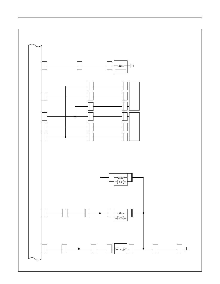
Circuit Diagram (RHD 6VE1)-2
D08RW611
FRT AXLE
SW
T.O.D. CONTROL UNIT
3
C-16
FENDER-LH
M-22
0.5
L/Y
0.5
G
0.5
G/W
0.5
G/R
0.5
G/Y
0.5
LB
0.5
G/R
0.5
G
0.5
G
0.5
G
0.5
G/W
0.5
G/R
0.5
G/R
0.5
G/Y
0.5
LB
0.5
L/Y
0.5
L/Y
0.5
BR/R
0.5
P
0.5
Y
0.5
Y
0.5
B
0.5
B
0.5
B
0.85
B
0.5
L/Y
2
M-22
5
H-10
1
22
B-68
5
H-12
10
H-10
2
M-23
1
M-23
3
H-10
B-67
5
H-7
2
FRT SPEED
SENSOR
(TRANSFER)
RR SPEED
SENSOR
(TRANSFER)
CLUTCH
SOLENOID
(TRANSFER)
M-24
1
M-24
2
A-3
3
H-49
B-67
7
6
A-3
14
H-49
B-68
12
10
A-3
13
H-49
2
H-49
7
H-49
B-67
10
5
A-3
9
A-3
1
A-3
12
H-49
B-68
11
8
A-3
H-49
B-67
4
4
VSV;
FRT AXLE(C)
VSV;
FRT AXLE(D)
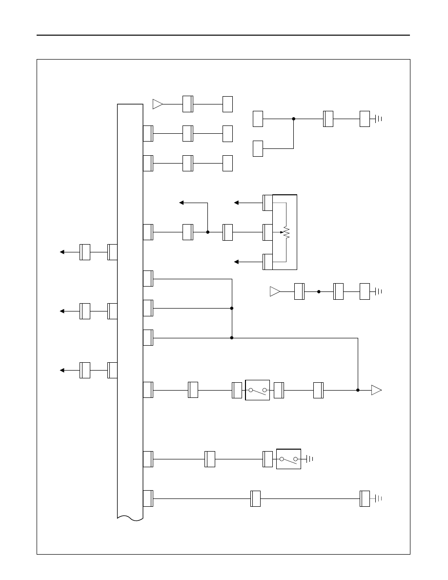
WIRING SYSTEM
8D–545
Circuit Diagram (RHD 6VE1)-3
D08RW612
4H SW
(TRANSFER)
T.O.D. CONTROL UNIT
7
A-3
TRANSFER
9
H-49
A-3
0.5
B/L
0.85
B
4
A-3
6
H-49
5
H-49
3
H-49
8
B-67
0.85
B
0.5
GR/R
0.5
GR/L
0.5
GR/L
0.5
B
0.5
B/L
0.5
GR/R
12
B-68
3
B-68
4
B-67
11
B-67
6
4L SW
(TRANSFER)
12
A-3
H-8
4
13
H-5
E-30
1.25
B/L
1.0
B/L
E-29
3
E-5
2
E-5
14
H-5
5
H-6
COMMON
CHAMBER
COMMON
CHAMBER
B-68
9
H-7
6
C-63
C-63
C-63
B-68
10
H-8
7
C-63
B-68
8
H-8
8
54
C-63
H-7
16
819
B
B
A
B-67
9
0.5
B/L
0.5
B/L
0.5
B/L
0.85
R/W
0.85
L
0.75
L
0.8
L
0.8
R
0.8
G
0.5
B/L
0.5
B/P
0.5
B/L
0.5
B/L
0.5
O/B
0.3
W
0.3
W
0.85
G/W
0.85
G/W
0.5
O/B
1.25
B/P
1.0
B/R
0.75
L
PCM
(E8)
PCM
(A1)
PCM
(D8)
6
B-68
EHCU
(27)
1
E-5
THROTTLE POSITION
SENSOR
DATA LINK
CONNECTOR
20
H-15
1
B-68
TAIL RELAY
(3)
3
H-15
0.3
G
0.5
LG/R
0.5
P
3
B-67
EHCU
(9)
EHCU : ELECTRONIC
HYDRAULIC
CONTROL UNIT
9
H-15
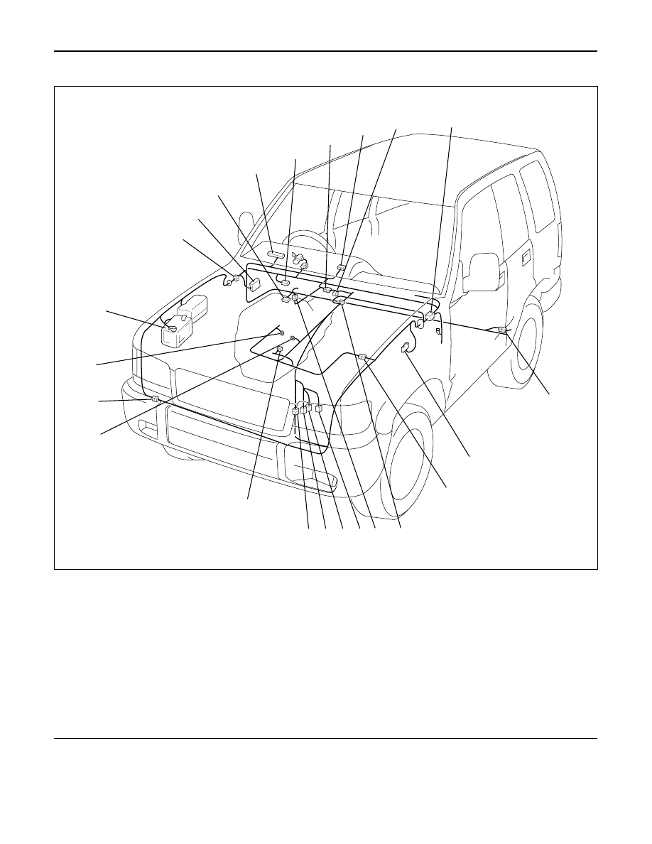
8D–546
WIRING SYSTEM
Parts Location
Legend
(1) I-9
(2) B-13 or B-14
(3) H-12
(4) I-12
(5) A-3
(6) H-7, H-8
(7) H-32
(8) C-16
(9) H-5, H-6
(10) C-63
(11) H-49
(12) M-22
(13) M-23
(14) M-24
(15) H-10
(16) E-5
(17) E-29
(18) H-42
(19) E-30
(20) Battery
(21) H-13, H-15, H-26
(22) Fuse Box
(23) B-67, B-68
D08RW621
1
2
3
4
5
8
7
9
10
11
12
13
14
15
16
17
18
19
20
21
22
23
6
WIRING SYSTEM
8D–547
Supplemental Restraint System (SRS) – Air Bag
General Description
The circuit consists of Sensing and Diagnostic Mod-
ule (SDM), driver’s air bag assembly, SRS coil assem-
bly, passenger’s air bag assembly, and “AIR BAG”
warning light. SDM, SRS coil assembly (driver side
only), driver air bag assembly, passenger air bag
assembly and connector wire make up the deploy-
ment loops. The function of the deployment loops is
to supply current through air bag assembly, which
will cause deployment of the air bags in the event of
a frontal crash of sufficient force, up to 30 degrees off
the center line of the vehicle. The air bag assemblies
are only supplied enough current to deploy when the
SDM detects vehicle velocity changes severe enough
to warrant deployment.
The SDM contains a sensing device which converts
vehicle velocity changes to an electrical signal.
The electrical signal generated is processed by the
SDM and then compared to a value stored in memory.
When the generated signal exceeds the stored value,
the SDM will cause current to flow through the air bag
assembly deploying the air bags.
Refer to Supplemental Restraint System in Restraints
section.
Нет комментариевНе стесняйтесь поделиться с нами вашим ценным мнением.
Текст