Opel Frontera UBS. Service manual — part 402
4JG2-NA/4JG2-TURBO ENGINE 6A 2– 29
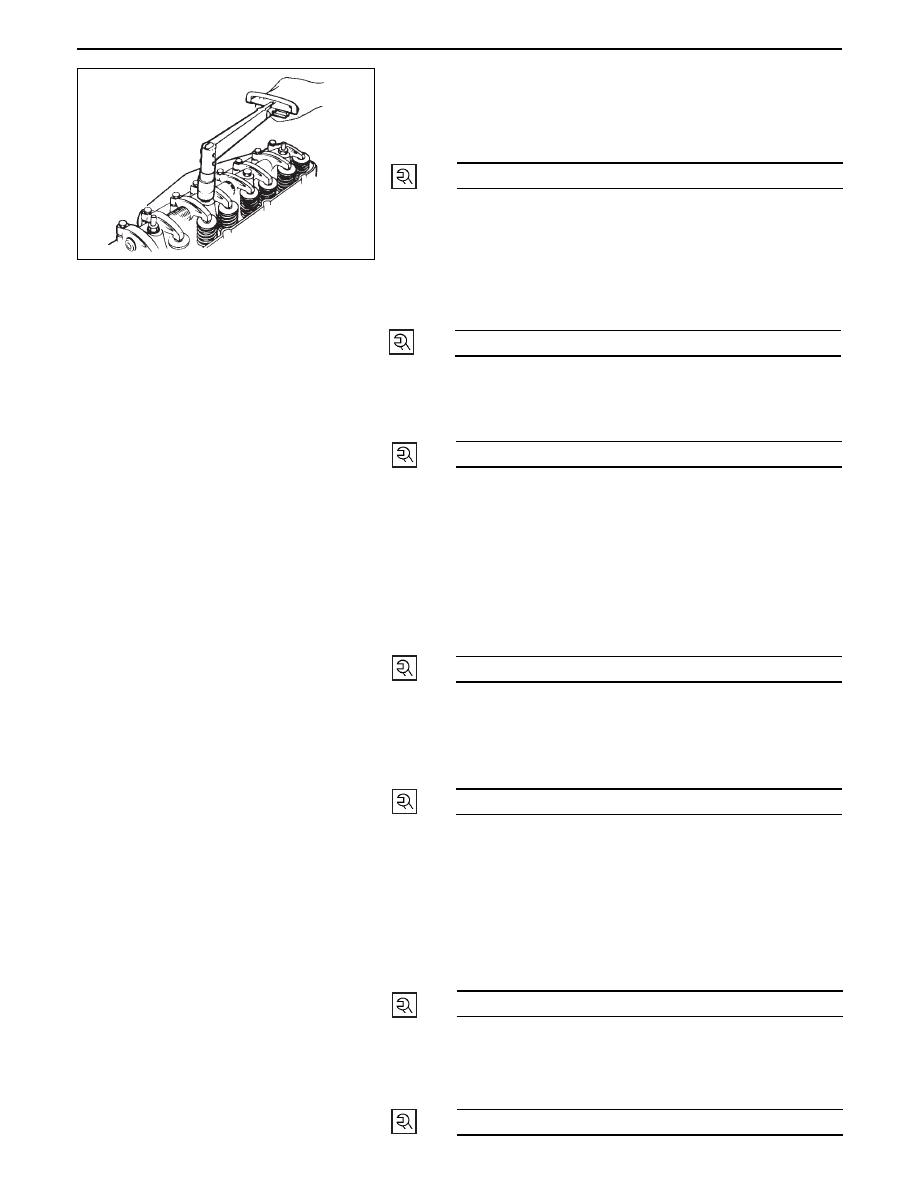
23. Rocker Arm Shaft Assembly
•
Loosen all adjusting screws.
•
Align fixing bolts to not of rocker arm shaft and
tighten them to the specified torque.
•
Valve clearance adjustment.
•
Refer to valve clearance adjustment steps in
section 00.
22. Fuel Leak Off Pipe
•
Install fuel leak off pipe with new copper gasket
and tighten joint bolts to the specified torque.
54 (5.5/40)
N·m (kg·m/lb·ft)
21. Injection Pipe
•
Install injection pipes and sleeve nuts securely and
tighten them to the specified torque.
29 (3.0/22)
N·m (kg·m/lb·ft)
29 (3.0/22)
N·m (kg·m/lb·ft)
20. Glow Plug Harness
19. Cylinder Head Cover
•
Apply engine oil to the rocker arms and the valve
spring.
•
Install the cylinder head cover gasket to the
cylinder head cover.
•
Tighten the cylinder head cover nuts to the
specified torque in the numerical order shown in
the illustration.
18. Fuel Leak Off Hose
17. Front Exh. Pipe
•
Install front exhaust pipe and tighten fixing bolts to
the specified torque.
13 (1.3/113)
N·m (kg·m/lb·in)
19 (1.9/14)
N·m (kg·m/lb·ft)
16. Exh. Manifold W/turbo (4JG2-T Only)
•
Install manifold gasket in cylinder head.
•
Insert exh. manifold into studs on cylinder head a
little.
•
Under this condition, insert oil return pipe frange
into studs on crankcase.
•
Tighten exh. manifold fixing bolts and nut to
specified torque.
26 (2.7/20)
N·m (kg·m/lb·ft)
15. Oil Cooler Hose
14. Oil Return Pipe: Turbo (4JG2-T Only)
•
Tighten joint bolt to the specified torque.
8 (0.8/69)
N·m (kg·m/lb·in)
6A2 – 30 4JG2-NA/4JG2-TURBO ENGINE
13. Oil Feed Pipe: Turbo (4JG2-T Only)
•
Tighten joint bolts (cylinder block and turbo
charger side) to the specified torque.
12. Water Outlet Hose: Turbo (4JG2-T Only)
•
Connect to water inlet pipe of engine.
11. Water Inlet Hose: Turbo (4JG2-T Only)
•
Connect to water outlet pipe.
10. Water Bypass Hose
•
Water bypass hose connect to water inlet pipe.
9.
Heater Hose
•
Connect to heater pipe.
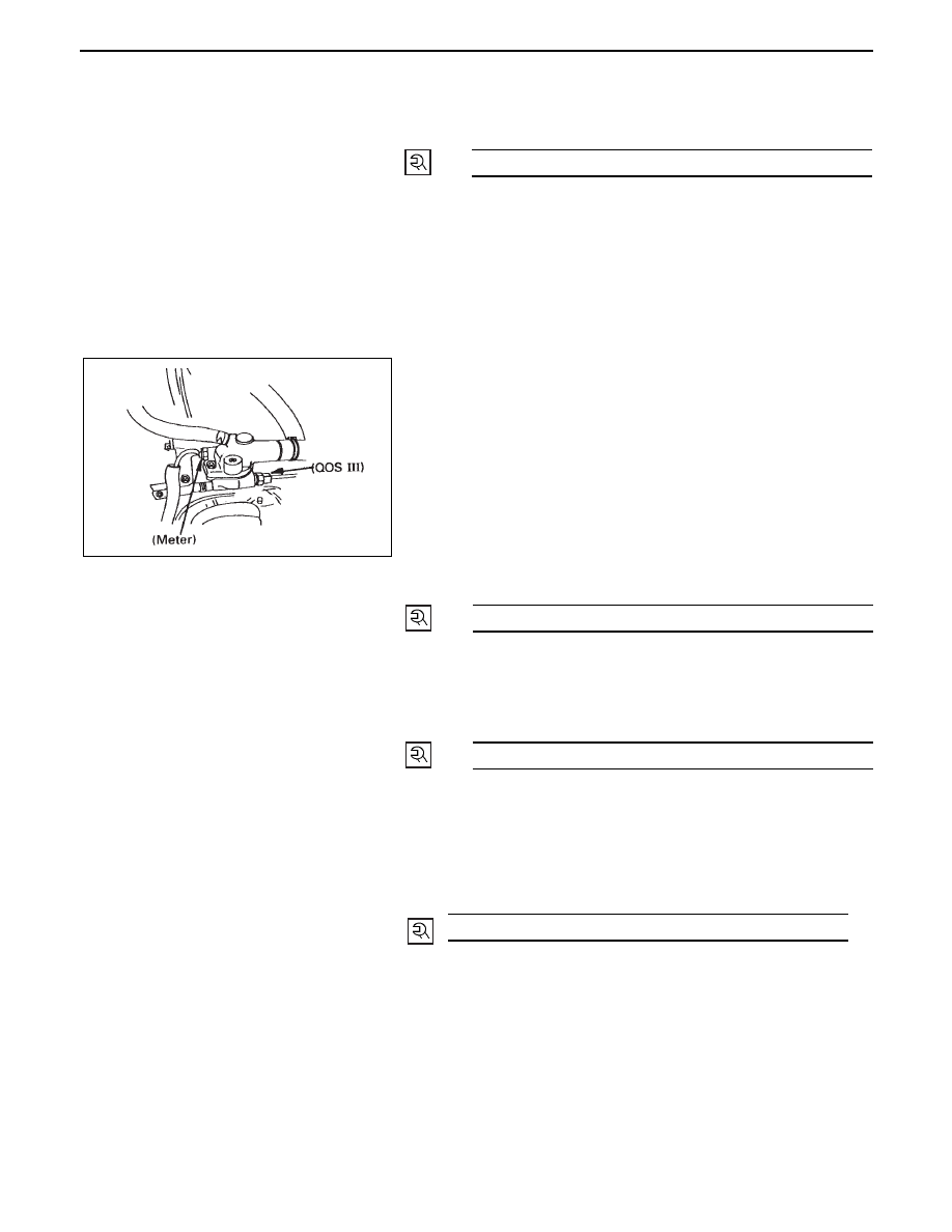
8.
Engine Harness
•
Connect five harness connecters to units on
thermostat housing.
7.
Water Hose: CSD
6.
A/C Compressor
•
Tighten temporarily fixing bolts (upper and front
lower sides of compressor.)
•
Tighten fixing bolt (rear under side of compressor)
to the specified torque by using a long extension
bar and torque wrench at under side of wheel arch.
•
Tighten fixing bolts (front upper and lower sides of
compressor) to the specified torque.
5.
P/S Pump Drive Belt
•
Install drive belts adjust belt tension by adjusting
bolt and tighten locking bolt to the specified
torque.
•
Refer to “Drive Belt Adjustment” in section 6B.
4.
Oil Level Gauge Guide Tube
•
Tighten guide tube to the specified torque.
23 (23/17)
N·m (kg·m/lb·ft)
37 (3.8/27)
N·m (kg·m/lb·ft)
40 (4.1/30)
N·m (kg·m/lb·ft)
19 (1.9/14)
N·m (kg·m/lb·ft)
3.
Intercooler Assembly (4JG2-T Only)
•
Refer to “Drive Belt Adjustment” in section 6B.
2.
Intake Air Duct (4JG2-T Only)
1.
Radiator Hose Upper
•
Connect to water outlet pipe.
4JG2-NA/4JG2-TURBO ENGINE 6A2 – 31
CRANKCASE
REMOVAL
Preparation
•
Disconnect battery ground cable.
•
Lift up car.
•
Drain engine oil.
NOTE
•
Install drain plug with new gasket.
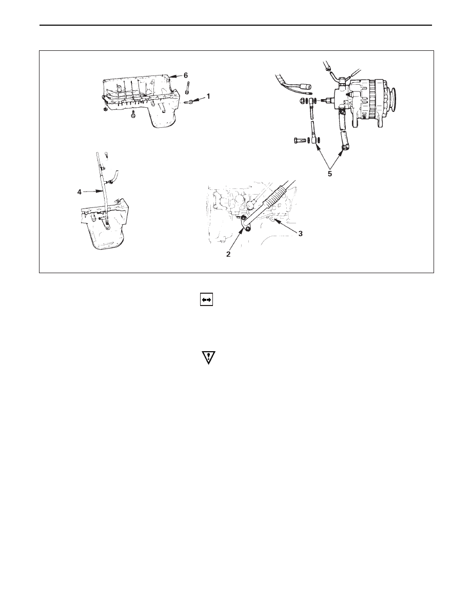
1. Transmission Housing Bolt
•
Remove six fixing bolts from under side of hous-
ing.
2. Oil Return Pipe: Turbo (4JG2 -T only)
•
Remove return pipe fixing nuts and set return pipe
frange from stud on crankcase.
3. Oil Pipe Clip Bolt: Vaccum Pump
4. Oil Level Gauge Guide Tube
•
Remove two guide tube stay fixing bolts.
•
Disconnect blow by hose and remove oil level
gauge guide tube.
6A2 – 32 4JG2-NA/4JG2-TURBO ENGINE
5. Vacuum Hose
6. Crankcase
•
Remove crankcase fixing bolts two fixing bolts for
rear oil seal arch parts on crankcase could be
removed extention universal joint box wrench.
•
Remove crankcase by using crankcase seal cutter
to shear sealant off and remove crankcase.
Oil seal cutter: 5-8840-2153-0
NOTE
•
Don’t ply crankcase or you may distort sealing
surface.
•
Distorted or damaged crankcase should not by
used.
INSTALLATION
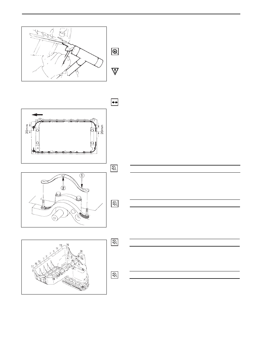
6.
Crankcase
•
Completely remove all sesidual sealant, lubricant
and moisture from the sealing surface of
crankcase and cylinder block.
•
Apply a correct width bead of sealant (TB-1207C or
its equivalent) to contact surface of crankcase
there must be no gaps in the bead.
•
Install crankcase with cylinder-block, and tighten
fixing bolts to the specified torque.
5. Vacuum Hose
4. Oil Level Gauge Guide Tube
•
Install guide tube to the specified torque.
•
Connect blow by hose to guide tube.
3. Oil Pipe Clip Bolts: Vacuum Pump
•
Tighten oil pipe clip fixing bolts to the specified
torque.
2. Oil Return Pipe: Turbo.
•
Tighten fixing nuts to crankcase to the specified
torque.
1. Transmission Housing Bolts
•
Pour engine oil into engine.
•
Install battery ground cable.
•
Start the engine and check for oil leakage from
crankcase.
19 (1.9/14)
N·m (kg·m/lb·ft)
19 (1.9/14)
N·m (kg·m/lb·ft)
19 (1.9/14)
N·m (kg·m/lb·ft)
8 (0.8/69)
N·m (kg·m/lb·in)
Нет комментариевНе стесняйтесь поделиться с нами вашим ценным мнением.
Текст