Opel Frontera UBS. Service manual — part 2474
6E–210
4JX1–TC ENGINE DRIVEABILITY AND EMISSIONS
Vehicle Speed Sensor (VSS)
Removal Procedure
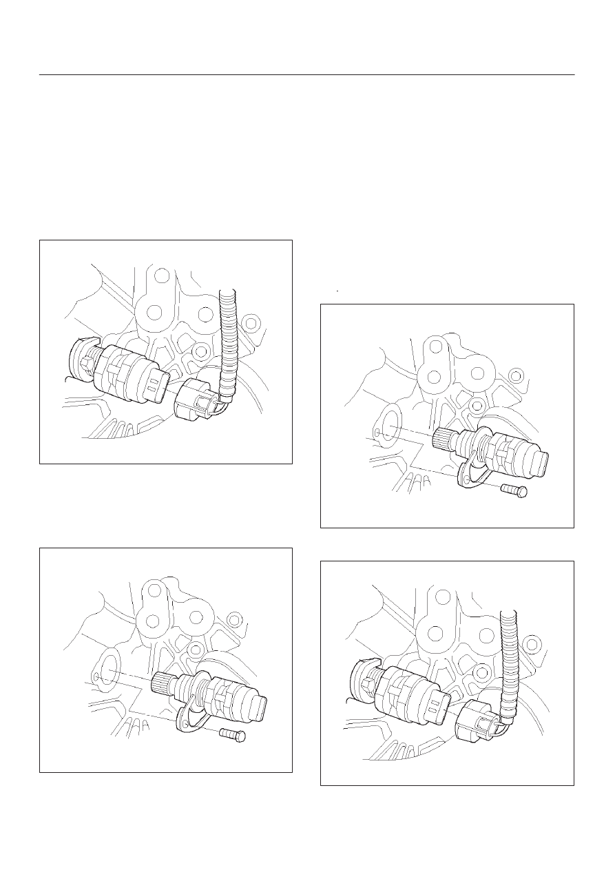
CAUTION: The VSS is located on the right side of
the transfer case just ahead of the rear propeller
shaft and very close to the exhaust pipes. Be sure
that the exhaust pipes are cool enough to touch
before trying to remove the VSS. If the pipes are hot,
you could be burned.
1. Disconnect the negative battery cable.
2. Disconnect the VSS electrical connector.
TS23748
3. Remove the bolt and the clamp securing the VSS in
place.
IMPORTANT:
Have a container ready to catch any fluid
that leaks out when the VSS is removed from the transfer
case.
TS23780
4. Remove the VSS from the transfer case by wiggling it
slightly and pulling it straight out.
Inspection Procedure
1. Inspect the electrical connector for signs of corrosion
or warping. Replace the VSS if the electrical
connector is corroded or warped.
2. Inspect the VSS driven gear for chips, breaks, or worn
condition. Replace the VSS if the driven gear is
chipped, broken or worn.
3. Inspect the O-ring for wear, nicks, tears, or
looseness. Replace the O-ring if necessary.
Installation Procedure
1. Install the VSS in the transfer case with the notch for
the connector facing the rear.
2. Secure the VSS in place with the clamp and the bolt.
Tighten
D
Tighten the bolt to 16 N·m (12 lb ft.).
TS23780
3. Connect the VSS electrical connector.
TS23748
4. Check the transfer case oil level. Add fluid if
necessary.
6E–211
4JX1–TC ENGINE DRIVEABILITY AND EMISSIONS
5. Connect the negative battery cable.
Air Cleaner/Air Filter
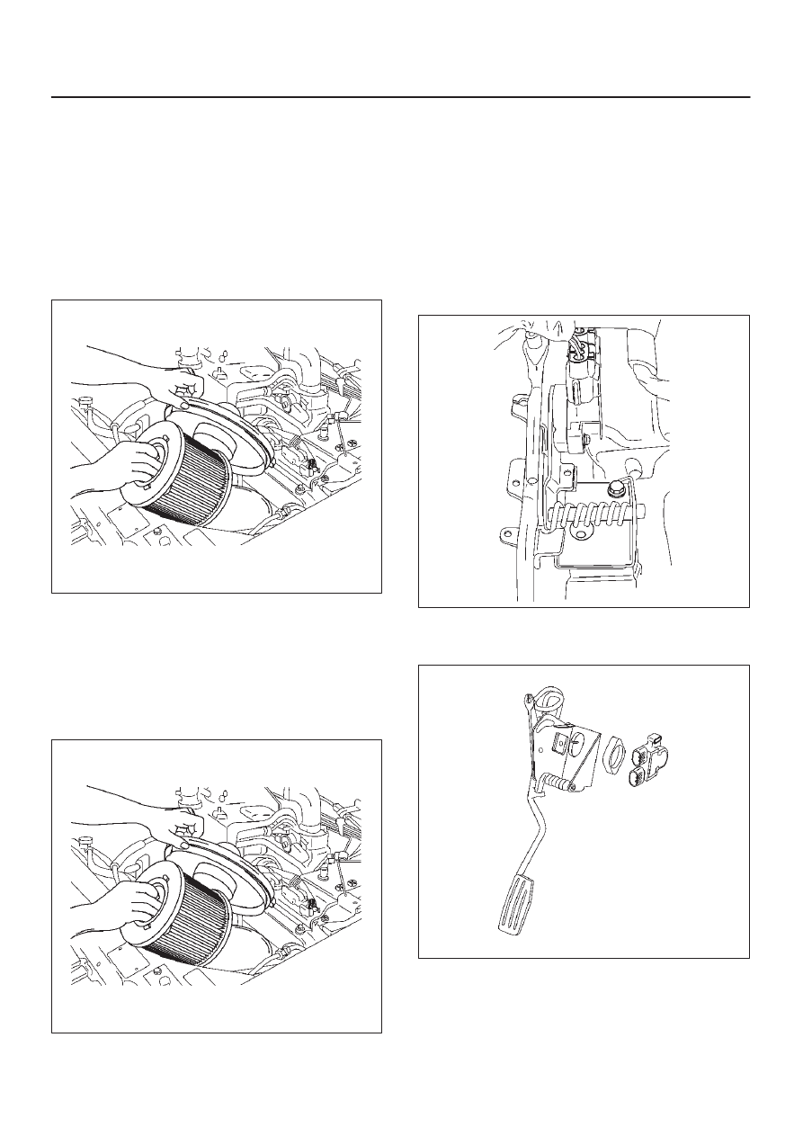
Removal Procedure
1. Loosen the clamp between the air cleaner lid and the
duct.
2. Release the four latches securing the lid to the air
cleaner housing.
3. Remove the air cleaner lid.
4. Remove the air filter element.
035RW074
5. Remove the retaining bolts and the air cleaner
housing from the vehicle.
Installation Procedure
1. Install the air cleaner housing in the vehicle with the
retaining bolts.
2. Install the air filter element in the air cleaner housing.
035RW074
3. Install the air cleaner lid on the air duct and the air
cleaner housing.
4. Tighten the clamp and secure the four latches
between the lid and the air cleaner housing.
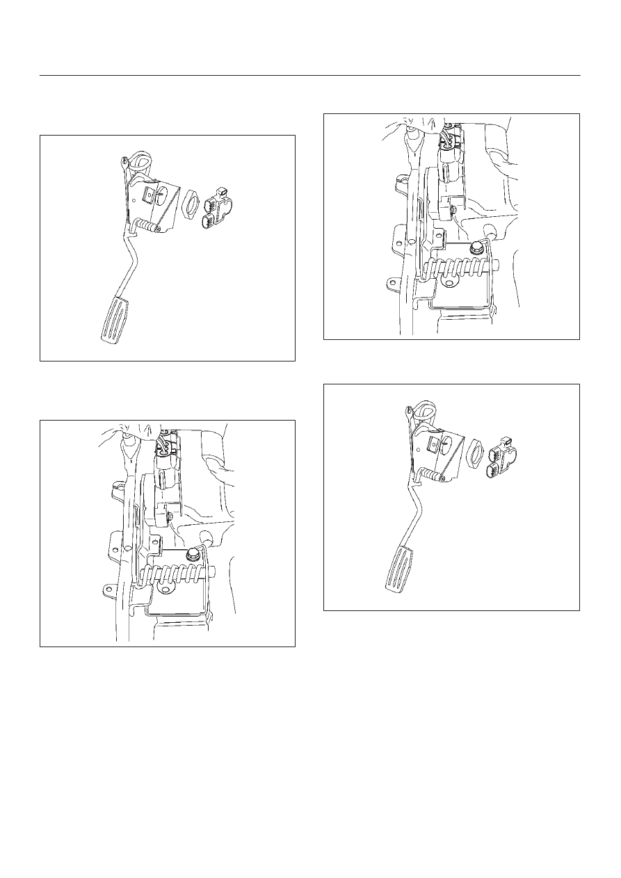
Accel Position (AP) Sensor
Removal Procedure
1. Disconnect the negative battery cable.
2. Disconnect the electrical connector to the AP sensor.
3. Remove the bolts and the accelerator pedal
assembly from the bulkhead.
035RW060
4. Remove the bolts and AP sensor from the accelerator
pedal assembly.
035RW066
6E–212
4JX1–TC ENGINE DRIVEABILITY AND EMISSIONS
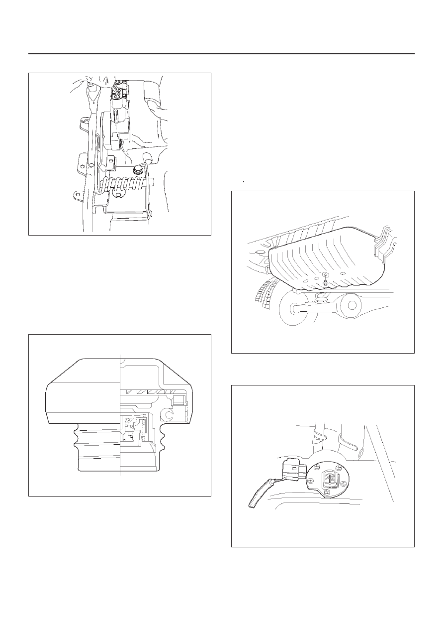
Installation Procedure
1. Install the AP sensor to the accelerator pedal
assembly.
035RW066
2. Install the accelerator pedal assembly to the
bulkhead.
3. Connect the electrical connector to the AP sensor.
035RW060
4. Connect the negative battery cable.
Accelerator Pedal Replacement
Removal Procedure
1. Disconnect the negative battery cable.
2. Disconnect the electrical connector to the AP sensor.
3. Remove the bolts and the accelerator pedal
assembly from the bulkhead.
035RW060
4. Remove the bolts and AP sensor from the accelerator
pedal assembly.
035RW066
Installation Procedure
1. Install the AP sensor to the accelerator pedal
assembly.
2. Install the accelerator pedal assembly to the
bulkhead.
6E–213
4JX1–TC ENGINE DRIVEABILITY AND EMISSIONS
3. Connect the electrical connector to the AP sensor.
035RW060
4. Connect the negative battery cable.
Fuel Filter Cap
General Description
The fuel filler cap includes a vacuum valve and a pressure
valve.
If high vacuum or high pressure occurs in the fuel tank,
each valve works to adjust the pressure in order to
prevent damage to the tank at the EGR valve.
TS23767
Inspection Procedure
NOTE: Replace the fuel filler cap with the same type of
filler cap that was originally installed on the vehicle.
D
Check the seal ring in the filler cap for any abnormality
and for seal condition.
D
Replace the filler cap if any abnormality is found.
Fuel Filter
Removal and Installation Procedure
Refer to the Engine fuel in the 4JX1 Engine section.
Fuel Gauge Unit
Removal Procedure
1. Disconnect the negative battery cable.
2. Loosen the fuel filler cap.
3. Drain the fuel from the tank.
Tighten
D
Tighten the drain plug to 20 N·m (14 lb ft.).
TS22907
4. Disconnect the wiring connector from the fuel gauge
unit.
TS23771
5. Remove the fuel gauge unit retaining screws.
Нет комментариевНе стесняйтесь поделиться с нами вашим ценным мнением.
Текст