Opel Frontera UBS. Service manual — part 430
6A – 10 ENGINE MECHANICAL
8. Check the engine oil level and replenish to the
specified level if required.
9. Start the engine and check for oil leakage from the
main oil filter.
FUEL SYSTEM
Fuel filter
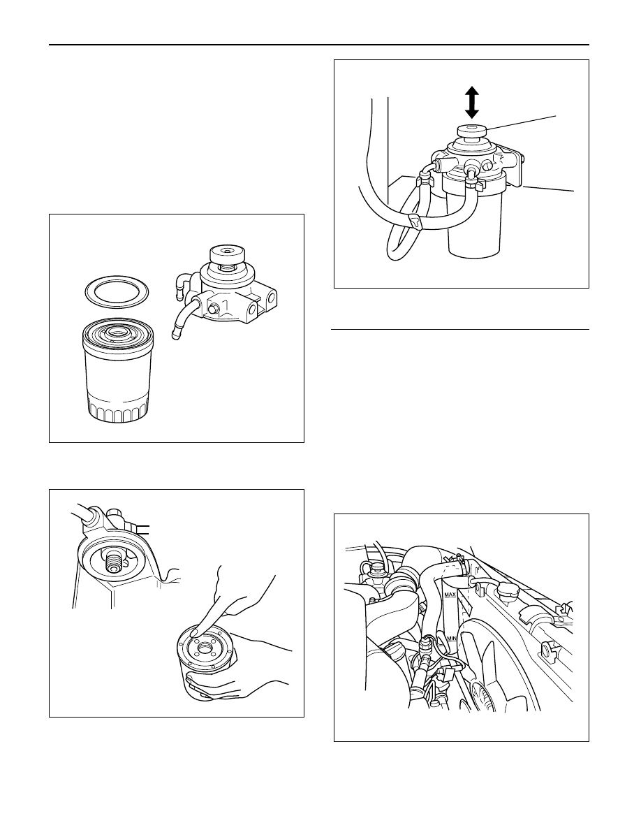
Replacement Procedure
1. Loosen the used fuel filter by turning it
counterclockwise with the filter wrench.
Filter Wrench : 5-8840-0203-0
2. Clean the filter cover fitting faces.
This will allow the new fuel filter to seat properly.
3. Apply a light coat of engine oil to the O-ring.
4. Turn the fuel filter until the sealing face comes in
contact with the O-ring.
5. Turn the fuel filter with a filter wrench 2/3 of a turn
until sealed.
Filter Wrench: 5-8840-0203-0
Legend
(1) Priming pump
6. Operate the priming pump until the air is discharged
completely from fuel system.
NOTE: The use of an Isuzu genuine fuel filter is
strongly recommended.
COOLING SYSTEM
Coolant Level
Check the coolant level and replenish the radiator
reserve tank as necessary.
If the coolant level falls below the “‘MIN” line, carefully
check the cooling system for leakage. Then add
enough coolant to bring the level up to the “MAX” line.
NOTE: Do not overfill the reserve tank.
012RW112
012RW078
1
012RW111
012RW080
ENGINE MECHANICAL 6A – 11
Remove the radiator filler cap only when absolutely
necessary.
Always check the coolant level when the engine is cold.
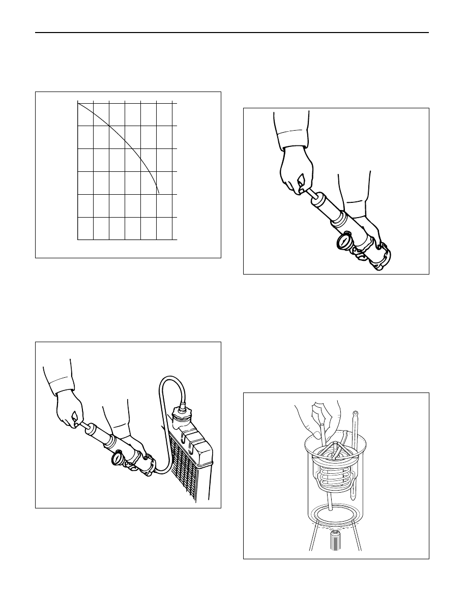
Always refer to the chart at the left to determine the
correct cooling water to antifreeze solution mixing ratio.
Cooling System Inspection
Install a radiator filler cap tester to the radiator. Apply
testing pressure to the cooling system to check for
leakage.
The testing pressure must not exceed the specified
pressure.
Testing Pressure: 196 kPa (2 kg/cm
2
/28.45 psi)
Radiator Cap Inspection
The radiator filler cap is designed to maintain coolant
pressure in the cooling system at 103 kPa (1.05
kg/cm
2
/15 psi).
Check the radiator filler cap with a radiator filler cap
tester.
The radiator filler cap must be replaced if it fails to hold
the specified pressure during the test procedure.
Radiator Filler Cap Pressure Valve: 88.2 – 117.6 kPa
(0.899 – 1.199 kg/cm
2
/12.8 – 17.1 psi)
Negative Valve (Reference): 1.0 – 3.9 kPa
(0.01 – 0.04 kg/cm
2
/0.14 – 0.57 psi)
Thermostat Operating Test
1. Completely submerge the thermostat in water.
2. Heat the water.
Stir the water constantly to avoid direct heat being
applied to the thermostat.
3. Check the thermostat initial opening temperature.
Thermostat Initial Opening Temperature:
83 – 87°C (181 – 189°F)
4. Check the thermostat full opening temperature.
Thermostat Full Opening Temperature:
100°C (212°F)
Valve Lift at Fully Open Position: 9.5 mm (0.374
in)
0
-10
-20
-30
-40
-50
-60
10
20
30
Mixing ratio (%)
F
reezing point (
°
C)
40
50
60
111RW002
110RS005
110RS006
031RS003
6A – 12 ENGINE MECHANICAL
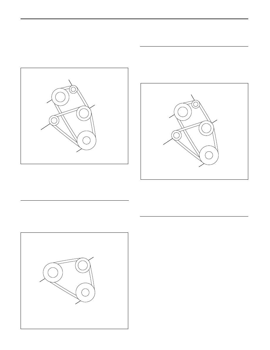
Drive Belt Adjustment
Check the drive belt tension
Depress the drive belt mid-portion with a 98 N (10 kg/
22 lb) force.
Drive Belt Deflection: 10 mm (0.39 in)
Check the drive belt for cracking and other damage.
Legend
(1) Crankshaft pulley
(2) Generator pulley
(3) Cooling fan pulley
(4) A/C compressor pulley
(5) Belt tensioner pulley
Cooling Fan Pulley Drive Belt
Fan belt tension is adjusted by moving the generator.
Depress the drive belt mid-portion with a 98 N (10 kg/
22 lb) force.
Legend
(1) Crankshaft pulley
(2) Generator pulley
(3) Cooling fan pulley
Compressor Pulley Drive Belt
Move the tensioner pulley as required to adjust the
compressor drive belt tension.
Depress the drive belt mid-portion with a 98 N (10 kg/
22 lb) force.
Legend
(1) Crankshaft pulley
(2) Generator pulley
(3) Cooling fan pulley
(4) A/C compressor pulley
(5) Belt tensioner pulley
5
3
2
4
1
012RW110
3
2
1
012RW084
5
3
2
4
1
012RW110
ENGINE MECHANICAL 6A – 13
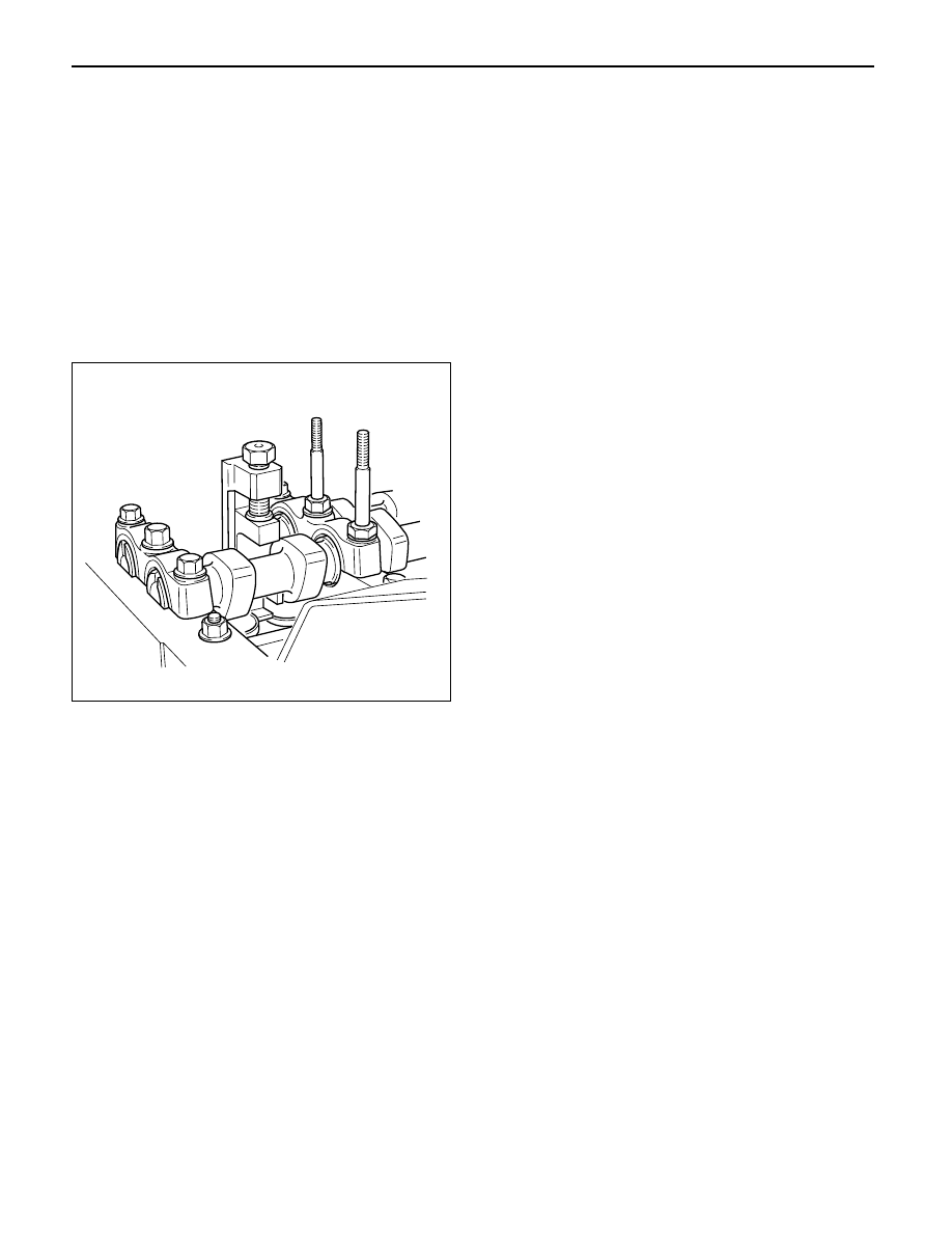
VALVE CLEARANCE ADJUSTMENT
1. Install 2.80 mm valve adjuster (shim) first when
reassembling the engine.
Thickness mark faces down.
2. Measure the valve clearance after installing cam
carrier assy with camshafts.
3. Change the adjuster using a special tool when the
clearance is out of tolerance.
Valve Clearance Adjusting Tool: 5-8840-2590-0
VALVE CLEARANCE (When cold condition)
Inlet
0.15 ± 0.05 mm
Exh
0.25 ± 0.05 mm
COMPRESSION PRESSURE
MEASUREMENT
1. Start the engine and allow it to idle until the coolant
temperature reaches 70 – 80°C (158 – 176°F).
2. Remove the following parts.
•
Glow plugs
•
Fuel cut solenoid connector
•
QOS (Quick-On Start System) fuse in the fuse
box.
3. Set the adapter and compression gauge to the No.
1 cylinder glow plug hole.
Compression Gauge
(with Adapter): 5-8840-2008-0
4. Turn the engine over with the starter motor and take
the compression gauge reading.
Compression Pressure at 200 rpm
Standard: 3040 kPa (31 kg/cm
2
/441 psi)
Limit: 2160 kPa (22 kg/cm
2
/313 psi)
5. Repeat the procedure (Steps 3 and 4) for the
remaining cylinders.
QUICK-ON START 4 SYSTEM
Quick-On Start System Inspection Procedure
1. Disconnect the ECT-sensor connection around the
thermostat outlet pipe.
2. Turn the starter switch to the “ON” position.
If the Quick-On Start 4 System is operating
properly, the glow relay will make a clicking sound
within seven seconds after the starter switch is
turned on.
3. Measure the glow plug terminal voltage with a
circuit tester immediately after turning the starter
switch to the “ON” position.
Glow Plug Terminal Voltage: approx. 12V
NOTE: Electrical power to the quick-on start system will
be cut after the starter has remained in the “ON”
position for twenty seconds.
Turn the starter switch to the “OFF” position and back
to the “ON” position.
This will reset the Quick-On Start 4 System.
014RW150
Нет комментариевНе стесняйтесь поделиться с нами вашим ценным мнением.
Текст