Opel Frontera UBS. Service manual — part 1238
6E–318
ENGINE DRIVEABILITY AND EMISSIONS
2. Remove the fuel pump relay from the underhood
relay box. Refer to
Fuel Pump Relay.
TS23976R
3. Start the engine and allow it to stall.
4. Crank the engine for 30 seconds.
5. Disconnect the negative battery cable.
Fuel Pump Assembly
Removal Procedure
1. Disconnect the negative battery cable.
2. Drain all the fuel from the tank.
3. Install and tighten the drain plug.
Tighten
D
Tighten the drain plug to 20 N·m (14 lb ft.).
4. Remove the fuel tank. Refer to
Fuel Tank.
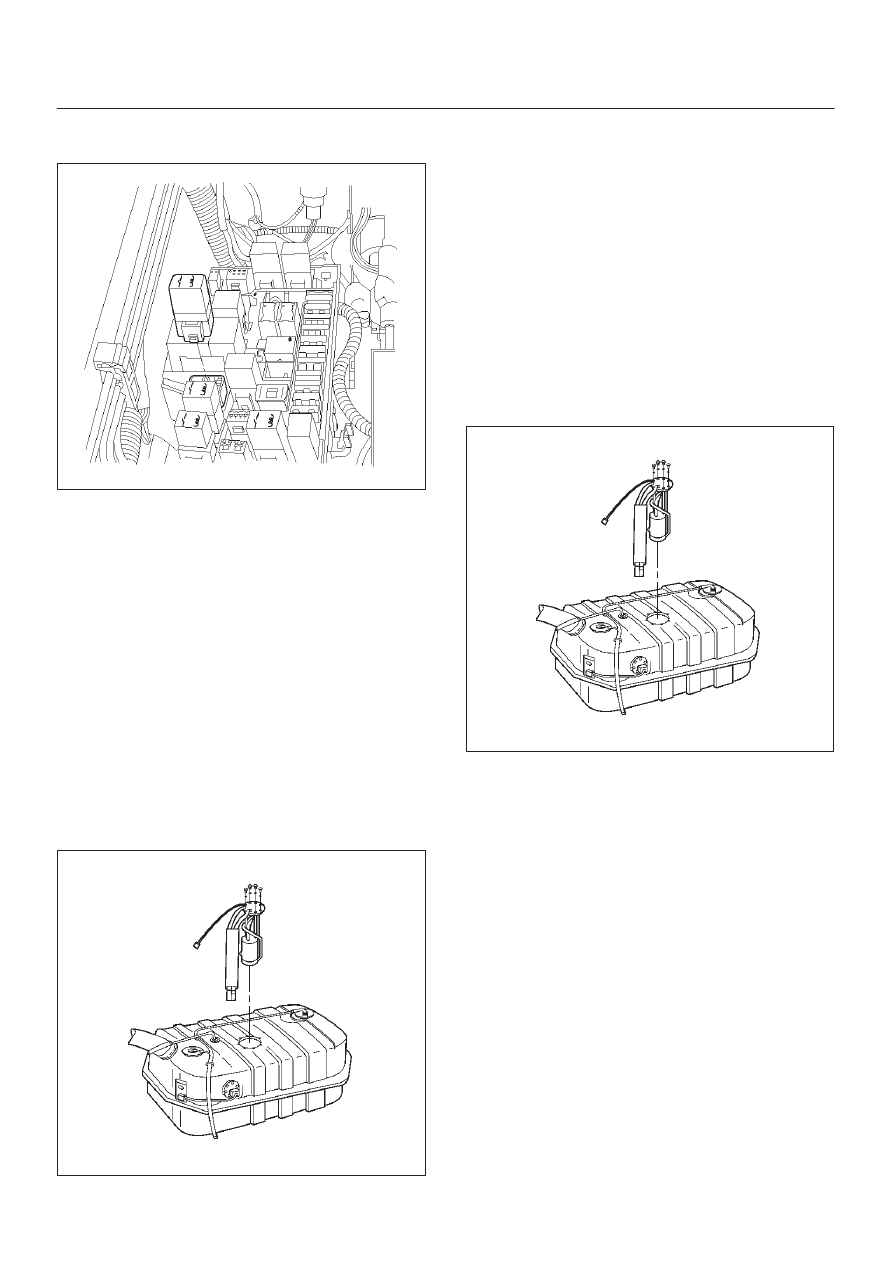
5. Remove the retaining screws from the fuel tank.
6. Remove the fuel pump assembly from the fuel tank.
D
Cover the fuel pump opening in order to prevent
dust, dirt, or debris from entering the fuel tank.
TS23795
Inspection Procedure
1. Inspect the fuel pump gasket for tears, cracks,
stretching, or rotting. If any of these conditions are
found, replace the fuel pump gasket.
2. Inspect the in-tank fuel filter for tears or evidence of
dirt, debris, or water in the fuel. If any of these
conditions are found, replace the in-tank fuel filter.
Installation Procedure
1. Install the fuel pump assembly.
2. Install the fuel pump assembly retaining screws.
3. Install the fuel tank assembly. Refer to
Fuel Tank.
4. Fill the tank with fuel.
5. Tighten the fuel filler cap.
6. Connect the negative battery cable.
TS23795
6E–319
ENGINE DRIVEABILITY AND EMISSIONS
Fuel Pump Relay
Removal Procedure
1. Remove the fuse and relay box cover from under the
hood.
2. Consult the diagram on the cover to determine which
is the correct relay.
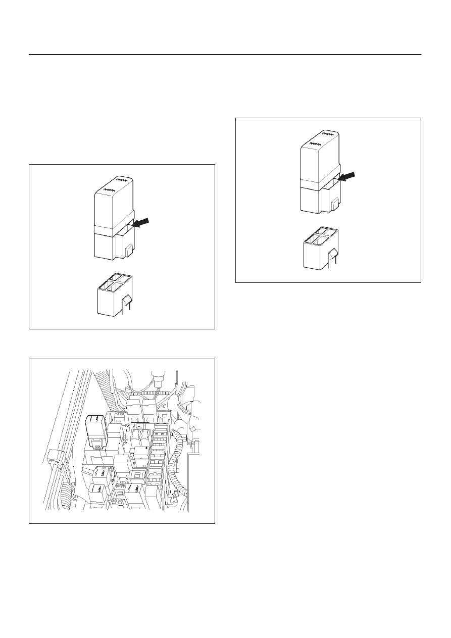
3. Insert a small screwdriver into the catch slot on the
forward side of the fuel pump relay.
D
The screwdriver blade will release the catch inside.
T321092
4. Pull the relay straight up and out of the fuse and relay
box.
TS23976R
Installation Procedure
1. Insert the relay into the correct place in the fuse and
relay box with the catch slot facing forward.
2. Press down until the catch engages.
D
An audible “click” will be heard.
T321092
3. Install the fuse and relay box cover.
Fuel Rail Assembly
Removal Procedure
NOTE:
D
Do not attempt to remove the fuel inlet fitting on the
fuel rail. It is staked in place. Removing the fuel inlet
fitting will result in damage to the fuel rail or the
internal O-ring seal.
D
Use care when removing the fuel rail assembly in
order to prevent damage to the injector electrical
connector terminals and the injector spray tips.
D
Fittings should be capped and holes plugged during
servicing to prevent dirt and other contaminants from
entering open lines and passages.
6E–320
ENGINE DRIVEABILITY AND EMISSIONS
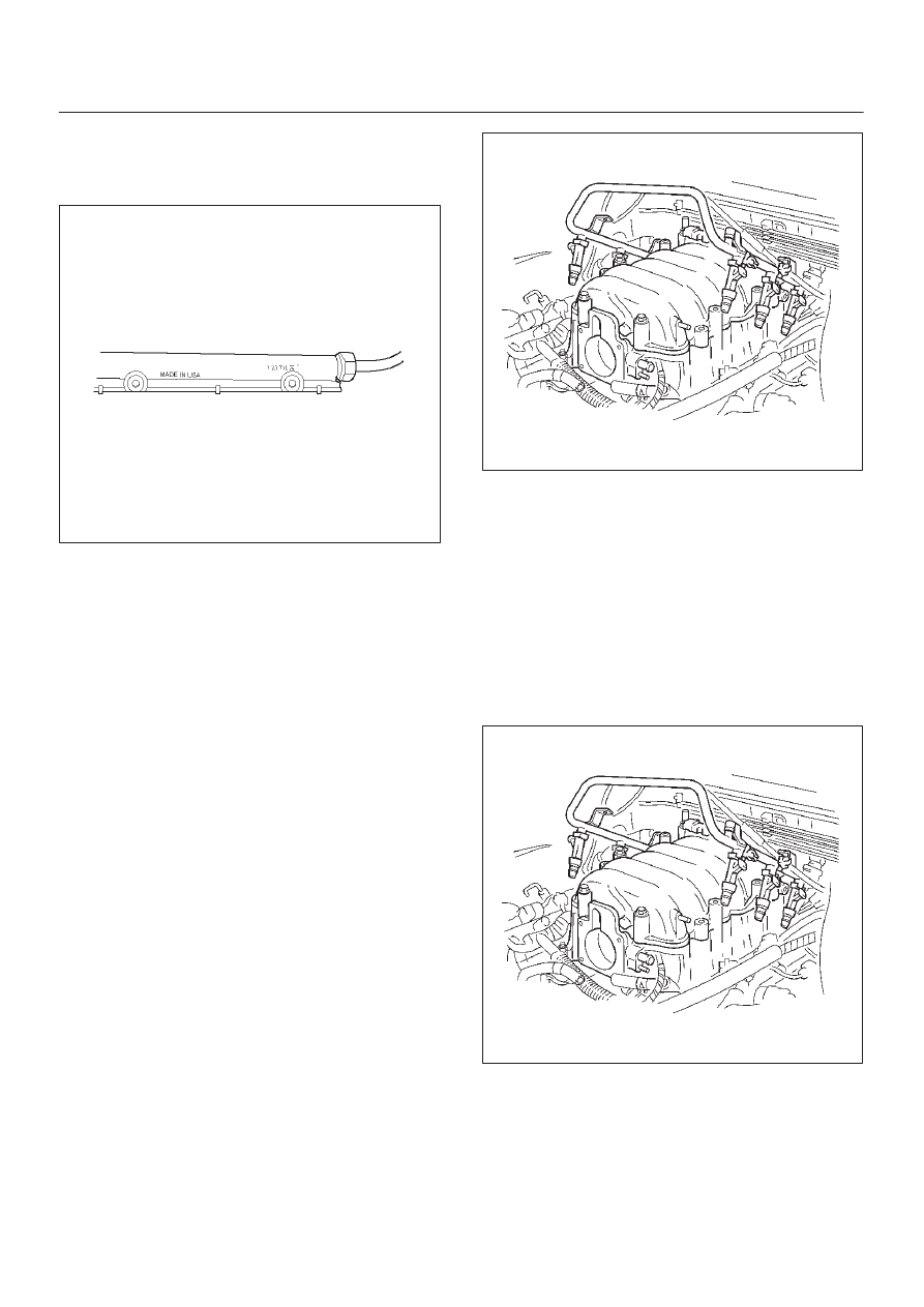
IMPORTANT:
An eight-digit identification number is
stamped on the side of the fuel rail. Refer to this number
when you service the fuel rail or when a replacement part
is required.
TS24022
Before removal, the fuel rail assembly may be cleaned
with a spray type engine cleaner. Follow the spray
package instructions. Do not immerse the fuel rails in
liquid cleaning solvent.
1. Depressurize the fuel system. Refer to Fuel Pressure
Relief Procedure in this Section.
2. Disconnect the negative battery cable.
3. Remove the engine cover.
4. Disconnect the accelerator pedal cable from throttle
body and cable bracket.
5. Disconnect the connectors from manifold absolute
pressure sensor, solenoid valve, electric vacuum
sensing valve.
6. Disconnect the vacuum hose on canister VSV and
positive crankcase ventilation hose.
7. Remove the common chamber. Refer to the common
chamber in Engine Mechanical.
1. Lift up carefully on the fuel injectors. Do not
separate the fuel injectors from the fuel rail.
2. If an injector becomes separated from the fuel
rail, the infector O-ring seals and the retainer clip
must be replaced.
3. Drain residual fuel into an approved container.
014RW164
8. If removal of the fuel pressure regulator is necessary,
refer to
Fuel Pressure Regulator.
9. If removal of the fuel injectors is necessary, refer to
Fuel Injectors.
Installation Procedure
1. If the fuel injectors were removed, install them. Refer
to
Fuel Injectors.
2. If the fuel pressure regulator was removed, install it.
Refer to
Fuel Pressure Regulator.
3. Install the common chamber. Refer to common
chamber in engine Mechanical.
014RW164
6E–321
ENGINE DRIVEABILITY AND EMISSIONS
4. Connect the vacuum hose on Canister VSV and
positive crankcase ventilation hose.
5. Connect the connectors to manifold absolute
pressure sensor, solenoid valve, electric vacuum
sensing valve.
6. Connect the accelerator pedal cable to throttle body
and cable bracket.
7. Install the engine cover.
8. Connect the negative battery cable.
9. Crank the engine until it starts. Cranking the engine
may take longer than usual due to trapped air in the
fuel rail and in the injectors.
Fuel Tank
Removal Procedure
1. Disconnect the negative battery cable.
2. Loosen the fuel filler cap.
3. Drain the fuel from the tank into an approved
container.
4. Install and tighten the drain plug.
Tighten
D
Tighten the drain plug to 20 N·m (14 lb ft.).
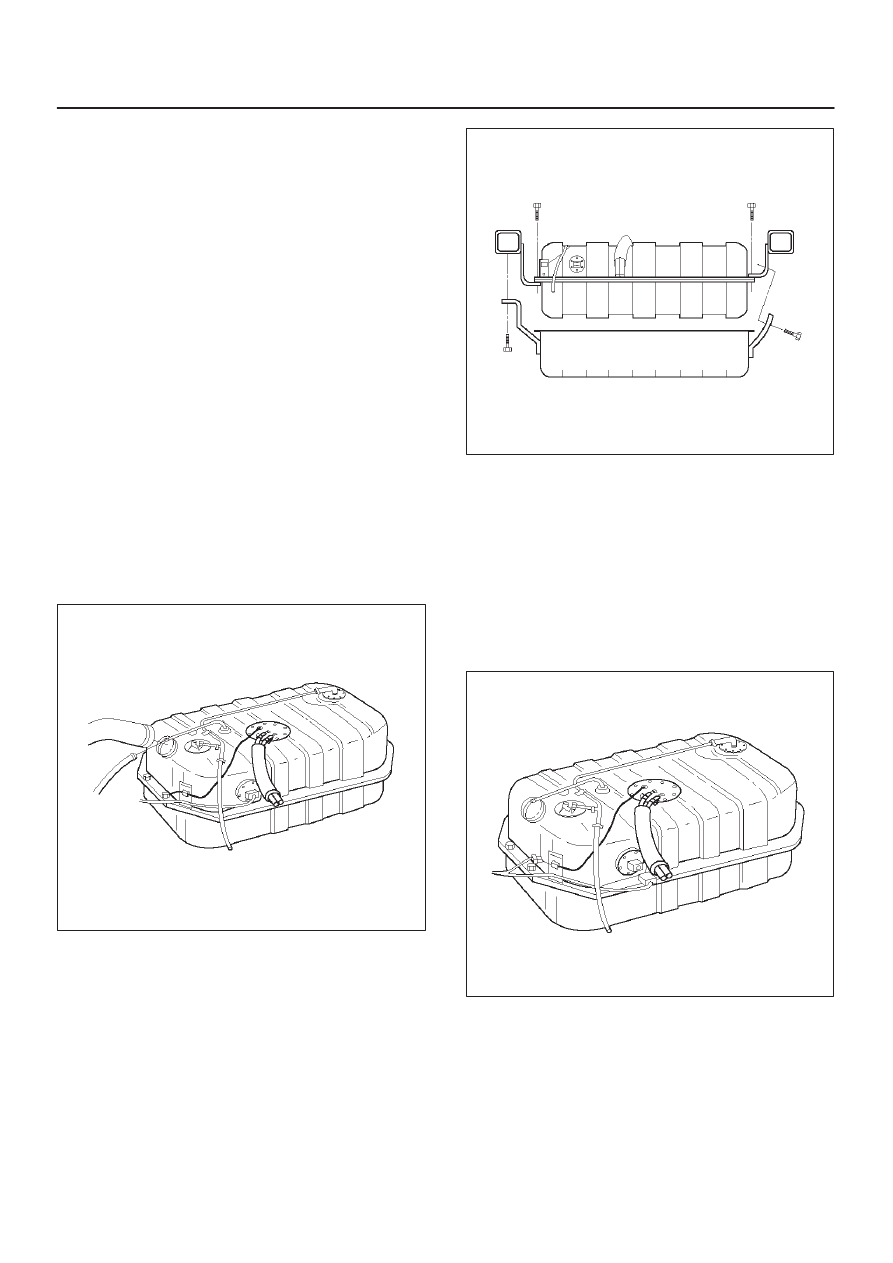
5. Disconnect the fuel filler hose at the fuel tank.
6. Disconnect the air breather hose at the fuel tank.
TS23796
7. Remove the undercover retaining bolts.
8. Remove the undercover.
TS23797
9. Disconnect the wiring connector to the fuel pump.
10. Disconnect the wiring connector to the fuel gauge
unit.
11. Remove the fuel gauge unit connector from the
bracket.
12. Disconnect the EVAP vapor hose.
13. Disconnect the fuel supply hose.
14. Disconnect the fuel return hose.
D
Plug the hoses to prevent dust from entering the
hoses.
TS23769
Нет комментариевНе стесняйтесь поделиться с нами вашим ценным мнением.
Текст