Opel Frontera UBS. Service manual — part 1360
6E–34
4JX1–TC ENGINE DRIVEABILITY AND EMISSIONS
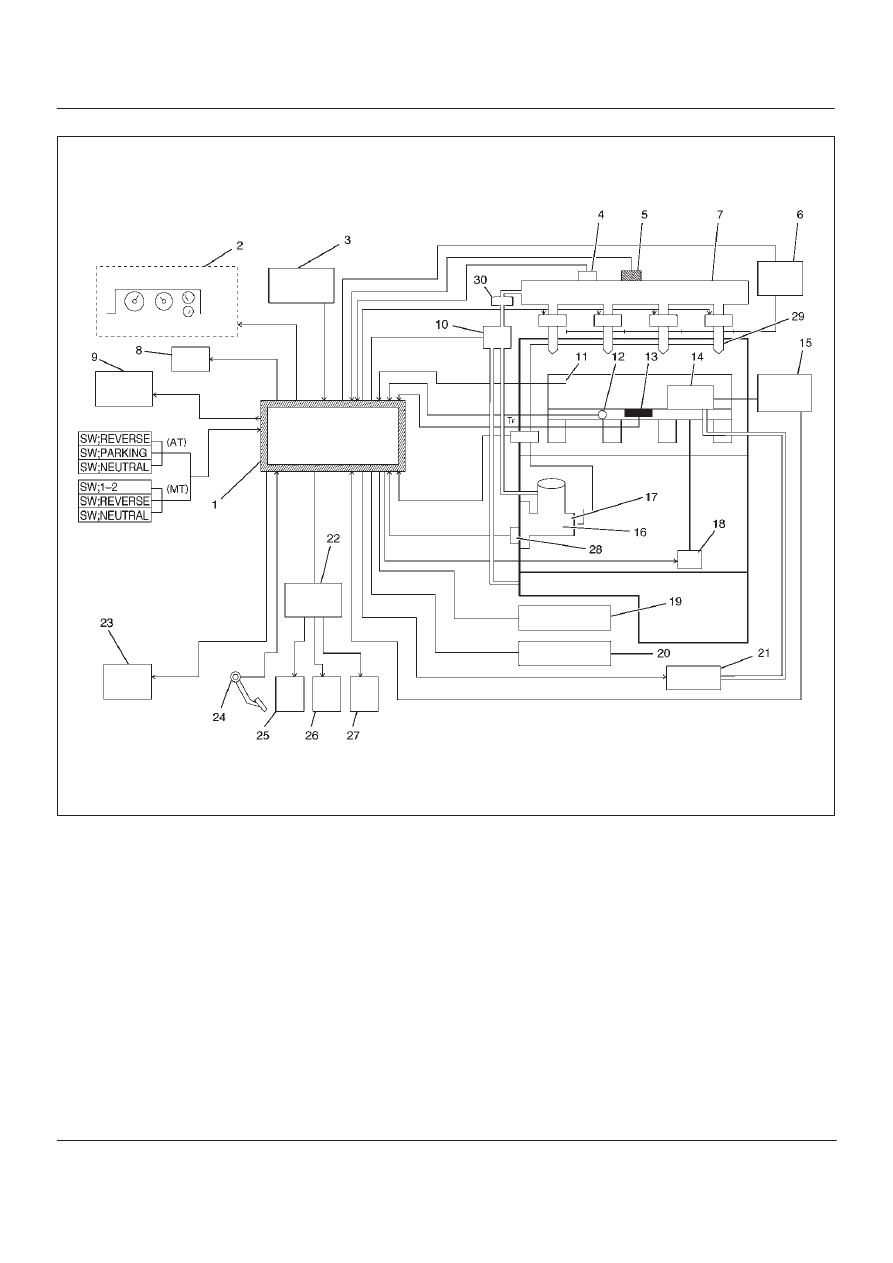
Fuel Injection System
060RW178
Legend
(1) ECM
(2) Meter Panel
(3) Battery
(4) Oil Temp Sensor
(5) Rail Pressure Sensor
(6) Glow Relay
(7) Oil Rail
(8) Tech–2
(9) A/C Comp Relay
(10) RPCV
(11) Intake Air Temp Sensor
(12) Engine Coolant Temp Sensor
(13) MAP Sensor
(14) EGR Valve
(15) EGR Pressure Sensor
(16) High Pressure Oil Pump
(17) Fuel Pump
(18) VSV
(19) EXH Throttle VSV1
(20) EXH Throttle VSV2
(21) EVRV
(22) Engine Harness Connector
(23) QWS Relay
(24) APS
(25) T.O.D
(26) ECT
(27) OBD
(28) TDC
(29) Injector
(30) Edge Filter
6E–35
4JX1–TC ENGINE DRIVEABILITY AND EMISSIONS
Guid to the System
D
Fuel Injection system is an HEUI (Hydraulically
Actuated, Electronically Controlled, Unit, Injector)
type. In this type of injector system, the oil
pressurized by means of High Pressure Oil Pump
(16) is fed through Rail Pressure Control Valve (10)
and Oil Rail (7) to Injector (29) from which fuel is
injected under this oil pressure.
For diagnosis, therefore, the Rail Pressure as well as
the Electric Circuit must be inspected.
On-Board Diagnostic (OBD) System Check
A Group
060RW135
6E–36
4JX1–TC ENGINE DRIVEABILITY AND EMISSIONS
B Group
060RW133
C Group
060RW129
6E–37
4JX1–TC ENGINE DRIVEABILITY AND EMISSIONS
D Group
060RW134
Circuit Description
The on-board diagnostic system check is the starting
point for any driveability complaint diagnosis. Before
using this procedure, perform a careful visual/physical
check of the ECM and engine grounds for cleanliness and
tightness.
The on-board diagnostic system check is an organized
approach to identifying a problem created by an
electronic engine control system malfunction.
Diagnostic Aids
An intermittent may be caused by a poor connection,
rubbed-through wire insulation or a wire broken inside the
insulation. Check for poor connections or a damaged
harness. Inspect the ECM harness and connector for
improper mating, broken locks, improperly formed or
damaged terminals, poor terminal-to-wire connection,
and damaged harness.
Test Description
Number(s) below refer to the step number(s) on the
Diagnostic Chart:
1. The MIL (“Check Engine” lamp) should be “ON”
steady with the ignition “ON”/engine “OFF.” If not,
Chart A-1 should be used to isolate the malfunction.
2. Checks the Class 2 data circuit and ensures that the
ECM is able to transmit serial data.
3. This test ensures that the ECM is capable of
controlling the MIL (“Check Engine” lamp) and the
MIL (“Check Engine” lamp) driver circuit is not
shorted to ground.
4. If the engine will not start, the
Cranks But Will Not
Run chart should be used to diagnose the condition.
7. A Tech 2 parameter which is not within the typical
range may help to isolate the area which is causing
the problem.
9. When the ECM is replaced, the characteristic data of
injector and rail pressure sensor should be inputted.
Нет комментариевНе стесняйтесь поделиться с нами вашим ценным мнением.
Текст