Opel Frontera UBS. Service manual — part 2319

6E–312
6VE1 3.5 ENGINE DRIVEABILITY AND EMISSIONS
DTC P0563 – System Voltage High
Step
Action
Value(s)
Yes
No
1
Was the “ON-Board Diagnostic (OBD) System Check”
performed?
—
Go to
Step 2
Go to
OBD
System
Check
2
Using a DVM, measure the battery voltage at the
battery.
Is the battery voltage less than the specified value?
11.5 V
Go to
Step 3
Go to
Step 4
3
1. Charge the battery and clean the battery terminals.
2. Clean the battery ground cable connection if
corrosion is indicated.
Is the battery voltage less than the specified value?
11.5 V
Replace
battery
Go to
Step 4
4
1. Turn “OFF” all the accessories.
2. Install a Tech 2.
3. Select the ignition voltage parameter on the Tech 2.
4. Start the engine and raise the engine RPM to the
specified value.
Is the voltage more than 2.5 volts greater than the
measurement taken in step 2 or 3?
2000 RPM
Go to
Starting/
Charging
Go to
Step 5
5
Replace the PCM.
IMPORTANT: The replacement PCM must be
programmed. Refer to
On-Vehicle Service in
Powertrain Control Module and Sensors for
procedures.
And also refer to latest Service Bulletin.
Check to see if the Latest software is released or not.
And then Down Load the LATEST PROGRAMMED
SOFTWARE to the replacement PCM.
Is the action complete?
—
Verify repair
—

6E–313
6VE1 3.5L ENGINE DRIVEABILITY AND EMISSIONS
Diagnostic Trouble Code (DTC)
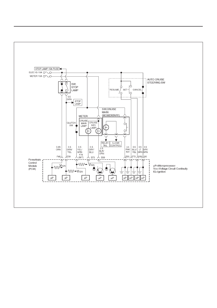
P0565 Cruise Main Switch Circuit Error
D06R200090
Circuit Description
The cruise control keeps the vehicle running at a fixed
speed until a signal canceling this fixed speed is received.
When the main switch is turned on with the vehicle in the
running mode, the battery voltage is applied to power train
control module(PCM). When a signal from the control
switch is input to PCM while the vehicle is in this state, the
cruise control system is activated. Also, while the PCM is
operating, the “CRUISE MAIN” indicator light in the meter
assembly lights up.
Conditions for setting the DTC
D
The Ignition is “ON’’.
D
Engine is running.
D
System voltage is between 11.5 volts and 16 volts.
D
The switch contact remains on for 15 seconds or more.
D
Noises are generated by poor switch contact 60 times
within 1 second.
Action Taken When the DTC Sets
D
The PCM will not illuminate the malfunction indicator
lamp (MIL).
D
The PCM will store conditions which were present
when the DTC was set in the Failure Records data only.
Conditions for Clearing the MIL/DTC
D
The PCM will turn the MIL “OFF” on the third
consecutive trip cycle during which the diagnostic has
been run and the fault condition is no longer present.
D
A history DTC P0565 will clear after 40 consecutive trip
cycle during which the warm up cycles have occurred
without a fault.
D
DTC P0565 can be cleared using the Tech 2 “Clear
Info” function or by disconnecting the PCM battery
feed.

6E–314
6VE1 3.5 ENGINE DRIVEABILITY AND EMISSIONS
Diagnostic Aids
An intermittent may be caused by the following:
D
Poor connections.
D
Mis routed harness.
D
Rubbed through wire insulation.
D
Broken wire inside the insulation.
Check for the following conditions:
D
Poor connection at PCM-Inspect harness connectors
for backed out terminals, improper mating, broken
locks, improperly formed or damaged terminals, and
poor terminal to wire connection.
D
Damaged harness-Inspect the wiring harness for
damage. If the harness appears to be OK, observe the
cruise main switch display on the Tech 2 while moving
connectors and wiring harnesses related to the sensor.
A change in the display will indicate the location of
the fault.
If DTC P0565 cannot be duplicated, the information
included n the Failure Records data can be useful in
determined vehicle mileage since the DTC was last
set.
If it is determined that the DTC occurs intermittently,
performing the DTC P0565 Diagnostic Chart may
isolate the cause of the fault.
DTC P0565 Cruise Main Switch Circuit Error
Step
Action
Value(s)
Yes
No
1
Was the “On-Board (OBD) System Check” performed?
—
Go to
Step 2
Go to
OBD
System
Check
2
1. Ignition “ON,” engine “ON.”
2. Observe the cruise main lamp in the switch.
Is the cruise main lamp “ON?”
—
Go to
Step 3
Go to
Step 4
3
1. Push the auto cruise main switch.
2. Observe the cruise main lamp in the switch.
Is the cruise main lamp “OFF?”
—
Check the
Procedure
Refer to
Diagnostic
Aids
Go to
Step 4
4
Check the signal circuit for auto cruise main switch.
1. Ignition is “OFF”.
2. Disconnect the powertrain control module(PCM).
3. Disconnect the cruise main switch.
Check for an open cruise main switch signal circuit
between the PCM and the cruise main switch.
Is a problem found?
—
Go to
Step 5
Go to
Step 6
5
Repair the auto cruise main switch signal circuit.
Is the action complete?
—
Verify repair
—
6
Check the auto cruise main switch and lamp circuit.
Is a problem found?
—
Go to
Step 7
Go to
Step 8
7
Repair or replace the auto cruise main switch and lamp
circuit.
Is the action complete?
—
Verify repair
—
8
Replace the PCM.
IMPORTANT: The replacement PCM must be
programmed.
Refer to
ON-Vehicle Service in Power Control Module
and Sensors for procedures.
And also refer to latest Service Bulletin. Check to see
if the latest software is released or not.
And then Down Load the LATEST PROGRAMMED
SOFTWARE to the replacement PCM.
Is the action complete?
—
Verify repair
—
6E–315
6VE1 3.5L ENGINE DRIVEABILITY AND EMISSIONS
Diagnostic Trouble Code (DTC)
P0566 Cruise Cancel Switch Circuit Error
D06R200090
Circuit Description
The cruise control keeps the vehicle running at a fixed
speed until a signal canceling this fixed speed is received.
When the main switch is turned on with the vehicle in the
running mode, the battery voltage is applied to powertrain
control module(PCM). When a signal from the control
switch is input to PCM while the vehicle is in this state, the
cruise control system is activated. Also, while the PCM is
operating, the “CRUISE MAIN” indicator light in the meter
assembly lights up.
When the cancel switch is “ON”, cruise system is “OFF”.
Conditions for setting the DTC
D
The Ignition is “ON”.
D
Engine is running.
D
System voltage is between 11.5 volts and 16 volts.
D
The switch contact remains on for 40 seconds or more.
D
Noises are generated by poor switch contact 100 times
within 1.6 seconds.
Action Taken When the DTC Sets
D
The PCM will not illuminate the malfunction indicator
lamp (MIL).
D
The PCM will store conditions which were present
when the DTC was set in the Failure Records data only.
Conditions for Clearing the MIL/DTC
D
The PCM will turn the MIL “OFF” on the third
consecutive trip cycle during which the diagnostic has
been run and the fault condition is no longer present.
D
A history DTC P0566 will clear after 40 consecutive trip
cycles during which the warm up cycles have occurred
without a fault.
Нет комментариевНе стесняйтесь поделиться с нами вашим ценным мнением.
Текст